Example of a pull flow
In this section we show you how to create a pull flow step by step and synchronize a data.
NOTE
Please, visit the Basic concepts section to become familiar with the main concepts of YouSolution.Cloud platform.
See the The data synchronization process to understand how the synchronization process takes place.
In this example, we want to synchronize data from a source node, called System A, and a target node, called System B.
The data that we are going to synchronize represents some information about a person, so the entity will be called Person and it will have the following format:
{
  "name": "John Smith",
  "age": 24,
  "address": "38235 Wisozk Park, Fort Lura, North Dakota"
}
The flow we are going to create is a pull flow so, when a data is synchronized by the platform, the target node has to make an http request to the platform to get the data.
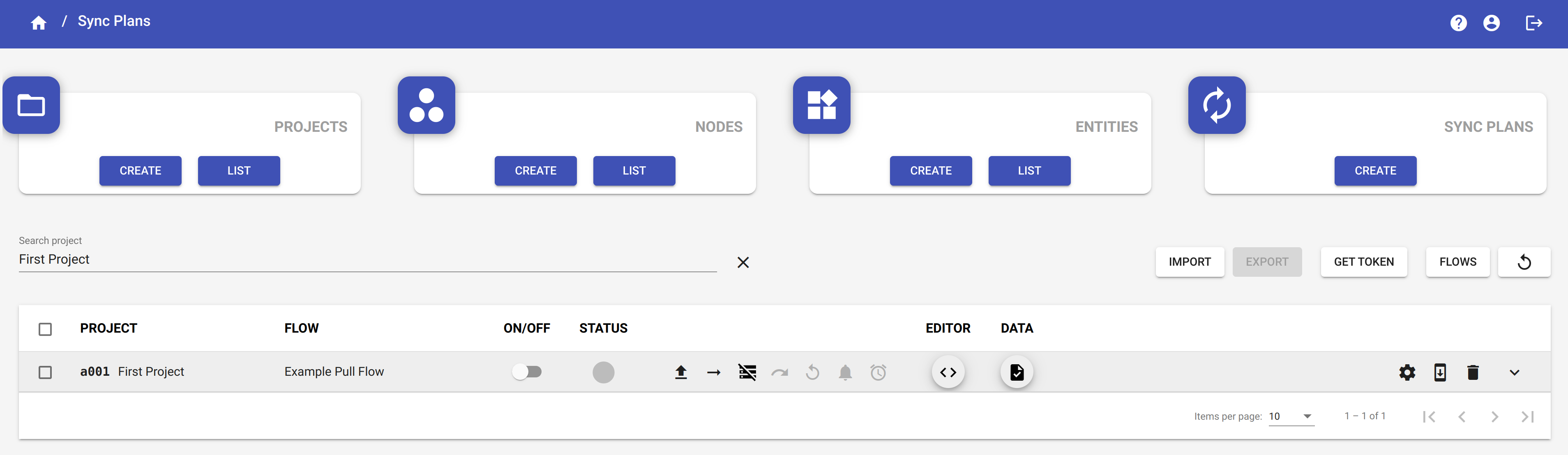
Click on the Dashboard button Sync Plans to access the Sync Plan page.
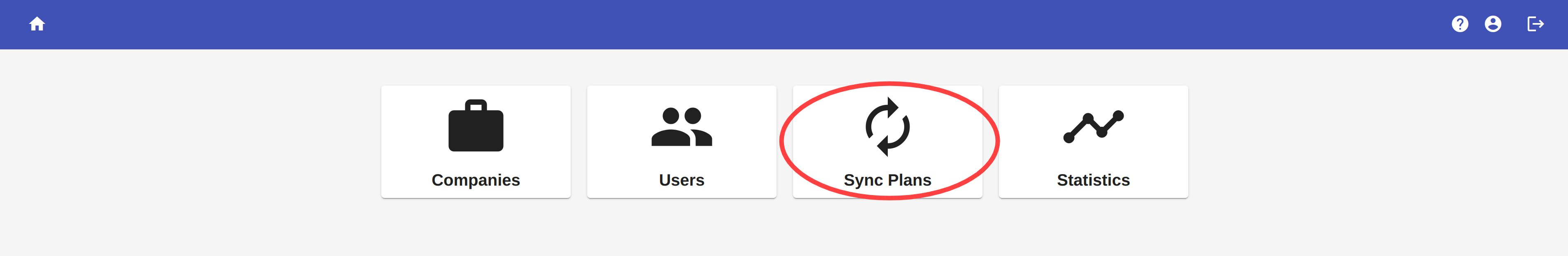
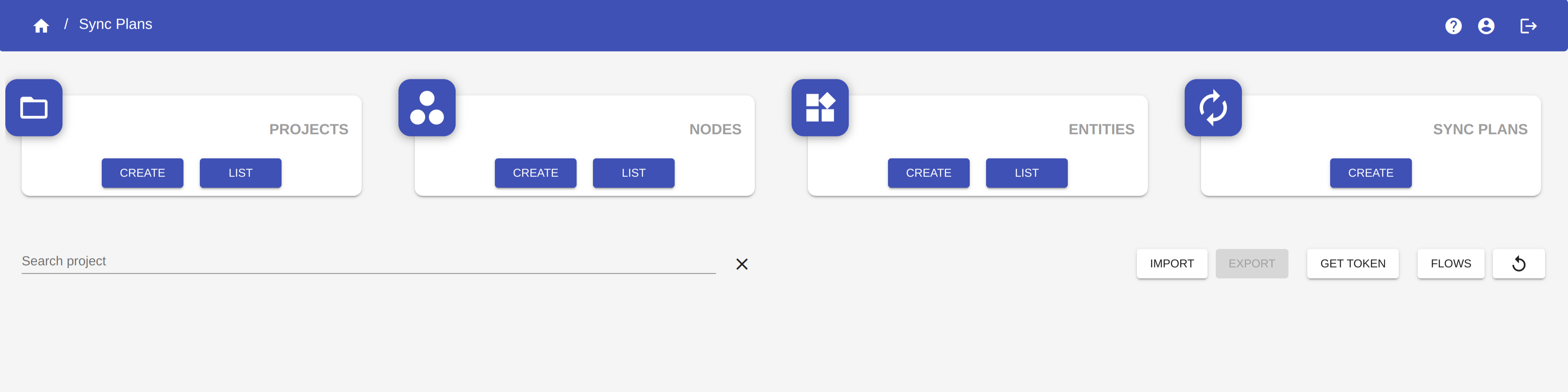
In this section you can find all the tools to create and manage your flows.
Create a project
A sync plan is contained in a project. Each project can contain one or more sync plans. So let's start by creating a project.
Click on the button CREATE in the Projects section to open the Project creation form.
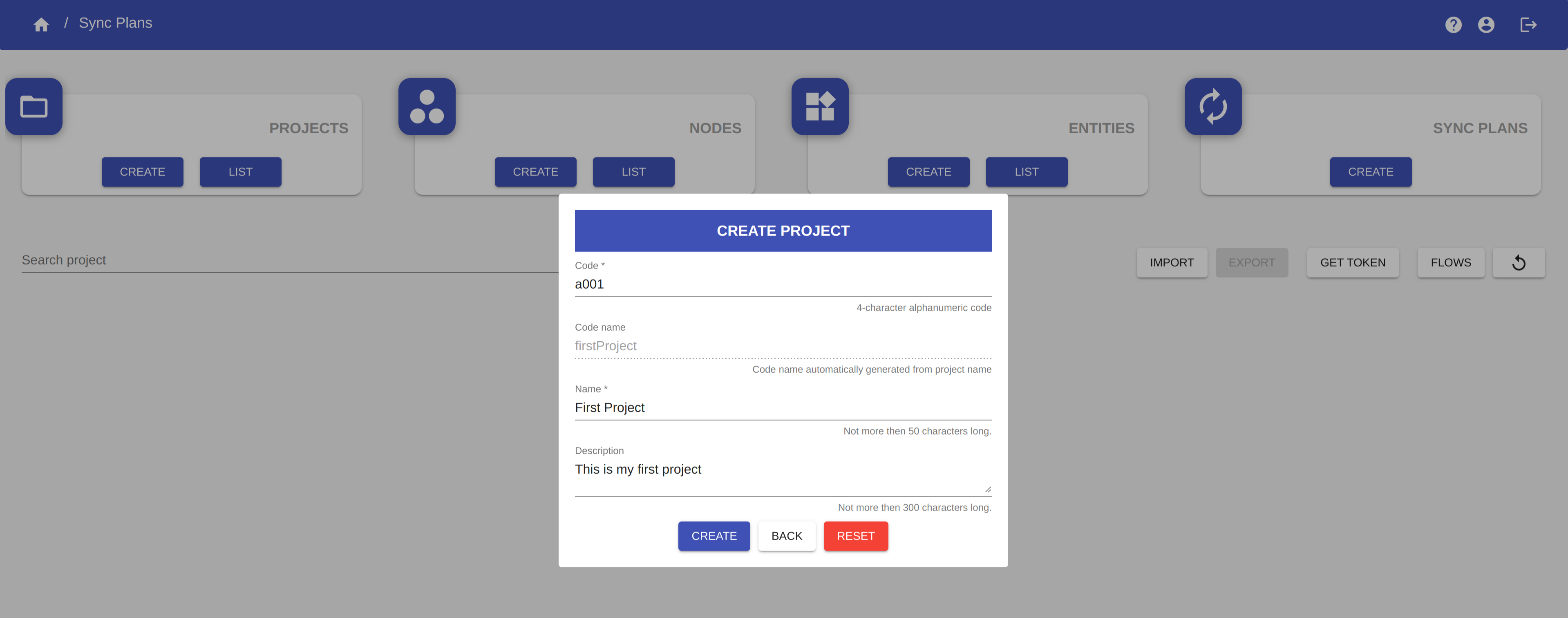
You have to fill in the following fields:
- Code: a 4-character alphanumeric code that uniquely identifies the project.
- Name: the name of the project.
- Description: an optional description of the project.
You don't have to fill in the Code name field. This is a field automatically generated from the Name field and it is used to uniquely identifies the project.
WARNING
The Name of the project must be unique.
EXAMPLE
Create a project with:
- code: a001
- name: First Project
Once you have completed the form, click on the button CREATE to create the project.
Create source node and target node
Click on the button CREATE in the Nodes section to open the Node creation form.
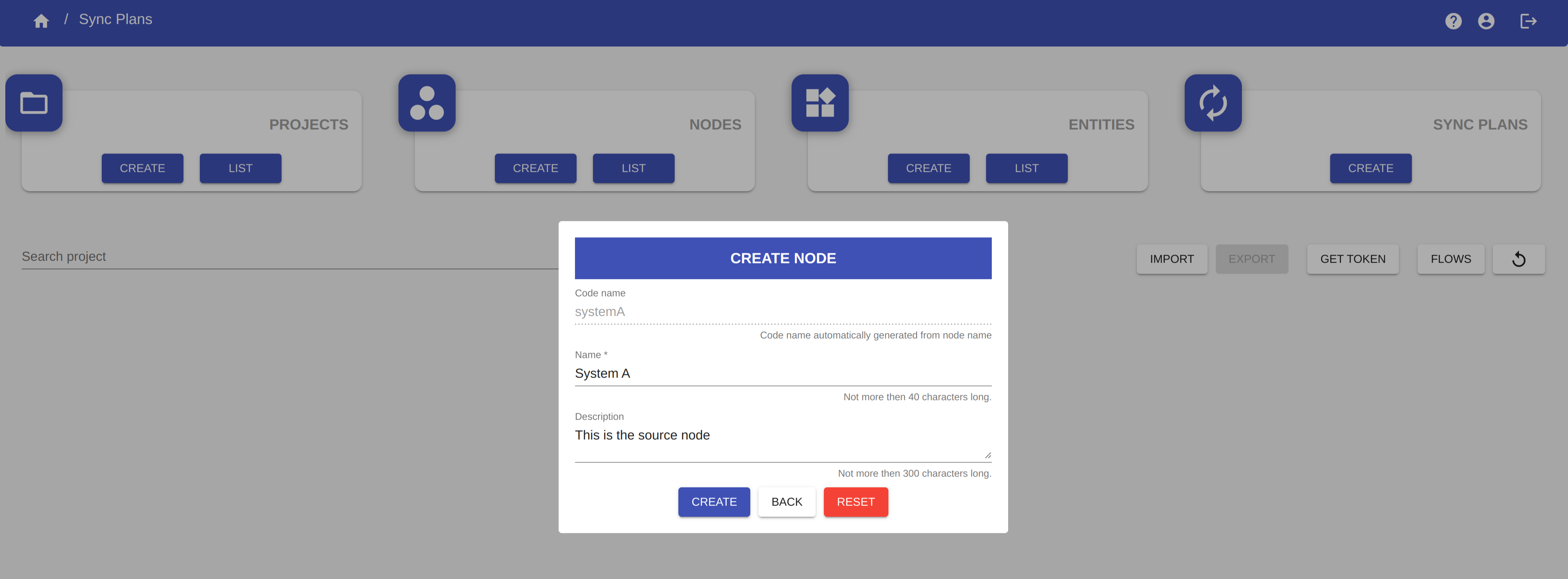
You have to fill in the following fields:
- Name: the name of the node.
- Description: an optional description of the node.
You don't have to fill in the Code name field. This is a field automatically generated from the Name field and it is used to uniquely identifies the node.
WARNING
The Name of the node must be unique.
EXAMPLE
Create a source node with name "System A" and a target node with name "System B".
Once you complete the form, click on the button CREATE to create the node.
Create entity
Click on the button CREATE in the Entities section to open the Entity creation form.

You have to fill in the following fields:
- Name: the name of the entity.
- Description: an optional description of the entity.
You don't have to fill in the Code name field. This is a field automatically generated from the Name field and it is used to uniquely identifies the entity.
WARNING
The Name of the entity must be unique.
EXAMPLE
Create an entity with name "Person".
Once you complete the form, click on the button CREATE to create the entity.
Create a sync plan
You can now create the sync plan. Our sync plan will be contained in the project First Project, will have a source node called System A, a target node called System B and an entity called Person.
Click on the button CREATE in the Sync Plan section to open the Sync Plan creation form.
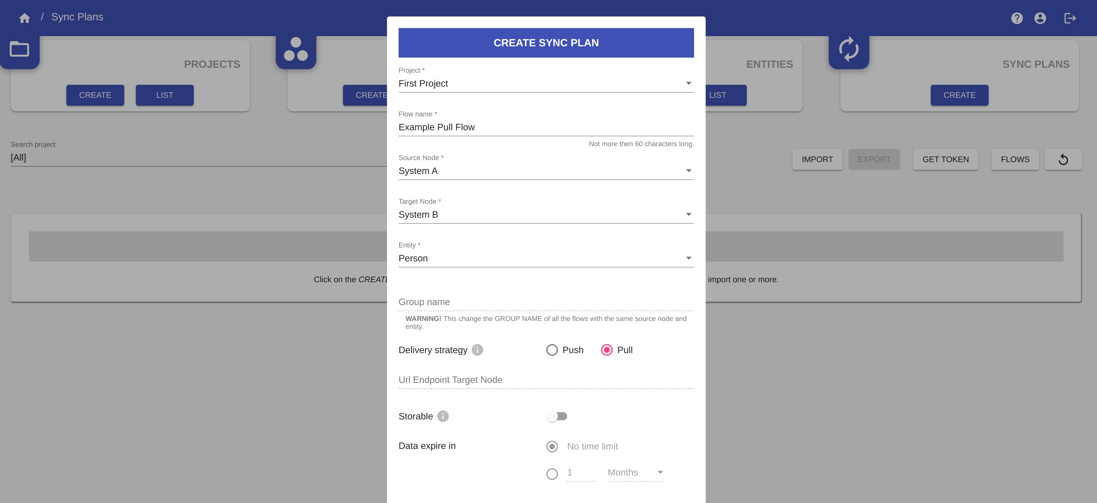
You have to fill in the following fields of the Sync Plan creation form:
- Project: select the project to which to associate the sync plan from the list of created projects.
- Flow name: the name of the sync plan.
- Source node: select a source node from the list of created nodes.
- Target node: select a target node from the list of created nodes.
- Entity: select an entity from the list of created entities.
- Delivery strategy: set the delivery strategy of the flow.
- Node-RED Tabs: insert one or more tab names that will be automatically created in Node-RED (see the section Node-RED).
WARNING
- The Source node - Entity combination must be unique.
- The Target node - Entity combination must be unique.
- The Source node - Target node - Entity combination must be unique.
WARNING
Delivery strategy option cannot be modified once the flow has been created.
EXAMPLE
Create a sync plan with these values:
- Project: select the project First Project previously created.
- Flow name: call this flow Example Push Flow.
- Source node: select the node System A previously created.
- Target node: select the node System B previously created.
- Entity: select the entity Person previously created.
- Delivery Strategy: select Pull.
- Node-RED Tabs: insert the strings Producer System A and Consumer System B. These are the names of the tabs that will be created in Node-RED and then we are going to edit by creating our own flows (see the section Node-RED).
Once you complete the form, click on the button CREATE to create the sync plan.
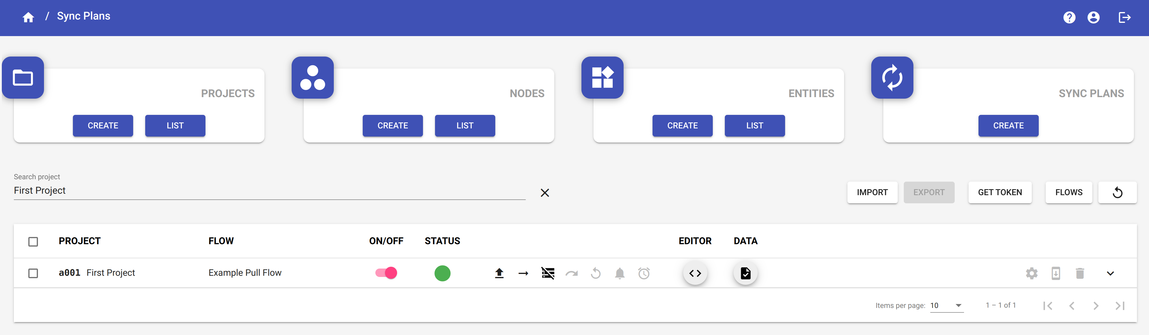
Now you can select the project named First Project from the Select project field to visualize all the sync plans which belog to that project.
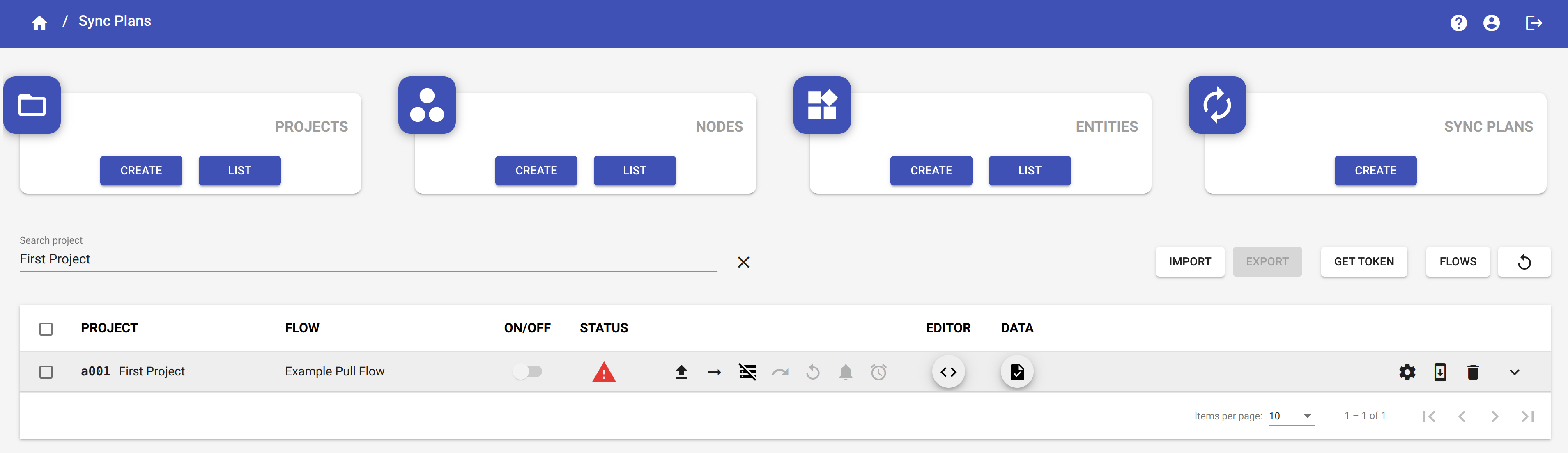
Here we can visualize the newly created sync plan.
In the STATUS column of the sync plan, you can see the icon ![]() which means that the code of the sync plan has not compiled yet.
which means that the code of the sync plan has not compiled yet.
The icon ![]() indicates that the flow has a push delivery strategy.
indicates that the flow has a push delivery strategy.
The next step is to write the code that defines the keys and the shared data through the editor and compile it.
Code editor
Click on the button ![]() in the EDITOR column of the sync plans table to access the editor.
in the EDITOR column of the sync plans table to access the editor.
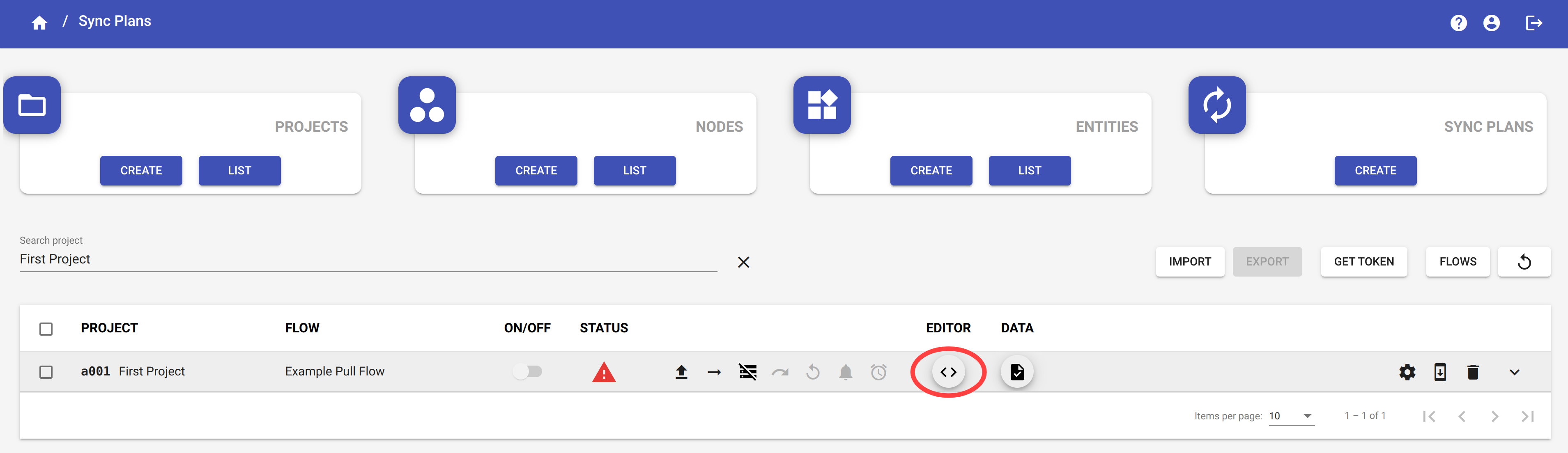
Here you can add or modify the typescript code of the sync plan.
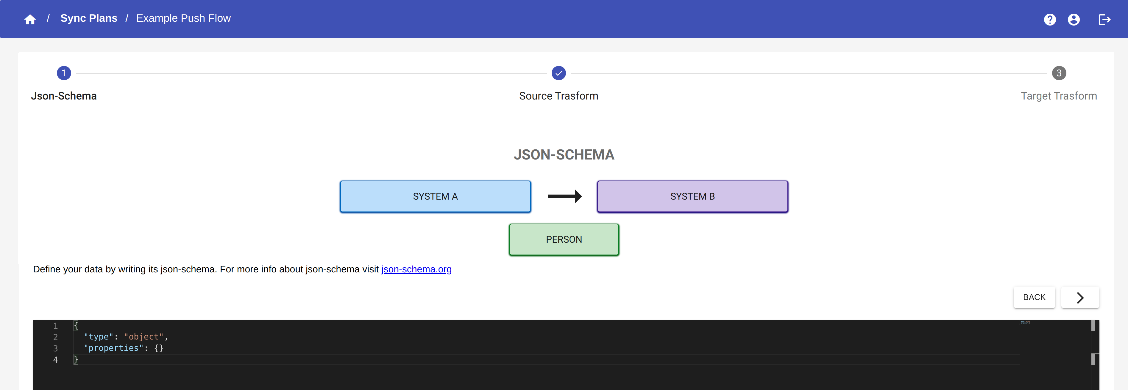
The editor is divided into three sections:
- Editor JSON Schema: define the format of the data.
- Editor Code Source Trasform From: extract the keys and the shared data from source node.
- Editor Code Target Trasform From: extract the keys and the shared data from target node.
JSON Schema
JSON Schema is an IETF standard providing a format for what JSON data is required for a given application and how to interact with it. It allows you to validate JSON documents.
For more info about JSON Schema visit json-schema.org
In this editor, you can define the format of the data which come from the source node.
NOTE
It is not necessary to define the JSON-Schema. You can avoid the validation of your data by adding an empty object in the JSON-Schema editor.
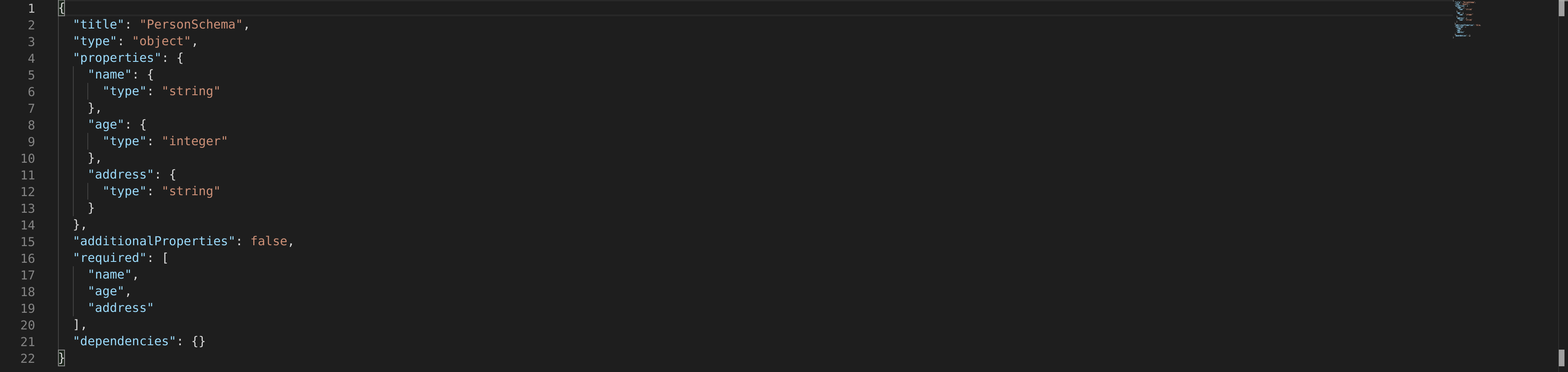
EXAMPLE - JSON Schema
In our example, the JSON Schema looks like the following:
Click on the button  to go on the next section of editor.
Code Source Transform From
The Code Source Transform From class is used to extrapolate the key fields from the source node and the data that you want to share and synchronize.
![]()
The method extractKeys returns an array of key fields. The parameter sourceData is the data sent from the source node to the YouSolution.Cloud platform, whose format has been previously defined with JSON Schema. In our example, we return the field "id" as the key of System A.
The method extractData returns an object whose properties are the data of the source node you want to share and syncronize with the target node. In our example, we want to synchronize the fields name and email of System A.
EXAMPLE - Code Source Transform From
Our Code Source Transform From looks like the following:
![]()
Click on the button to go on the next section of editor.
Code Target Transform From
The Code Code Target Transform From class is used to extrapolate the key fields from the target node and the data that you want to share and synchronize.
![]()
The method extractKeys returns an array of key fields. The parameter sourceData is the data sent from the target node to the YouSolution.Cloud platform. In our example, we return the field "retid" as the key of System B.
The method extractData returns an object whose properties are the data of the target node you want to share and syncronize with the source node. In our example, we extract all the fields of System B.
EXAMPLE - Code Target Transform From
Our Code Target Transform From looks like the following:
![]()
When you have finished editing the code, click on the button  . The code will be saved and compiled. Any compilation errors will be shown and, after correcting them, it will be possible to click again on the button to recompile the code.
Click on the button  to exit from editor.
In the Sync Plans page, if the code has been successfully compiled, you can see that the status icon has changed and turned grey.
Node-RED
To create your producers and consumers for sending and receiving data from the YouSolution.Cloud platform, you can use the integrated Node-RED tool.
Node-RED is a low-code programming tool for wiring together hardware devices, APIs and online services in new and interesting ways. It provides a browser-based editor that makes it easy to wire together flows using the wide range of nodes in the palette that can be deployed to its runtime in a single-click.
For more info about Node-RED visit nodered.org
Click on the button FLOWS to access Node-RED page.

When you access the Node-RED page, you will find the two tabs (Producer System A and Consumer System B) that have been created with the sync plan.
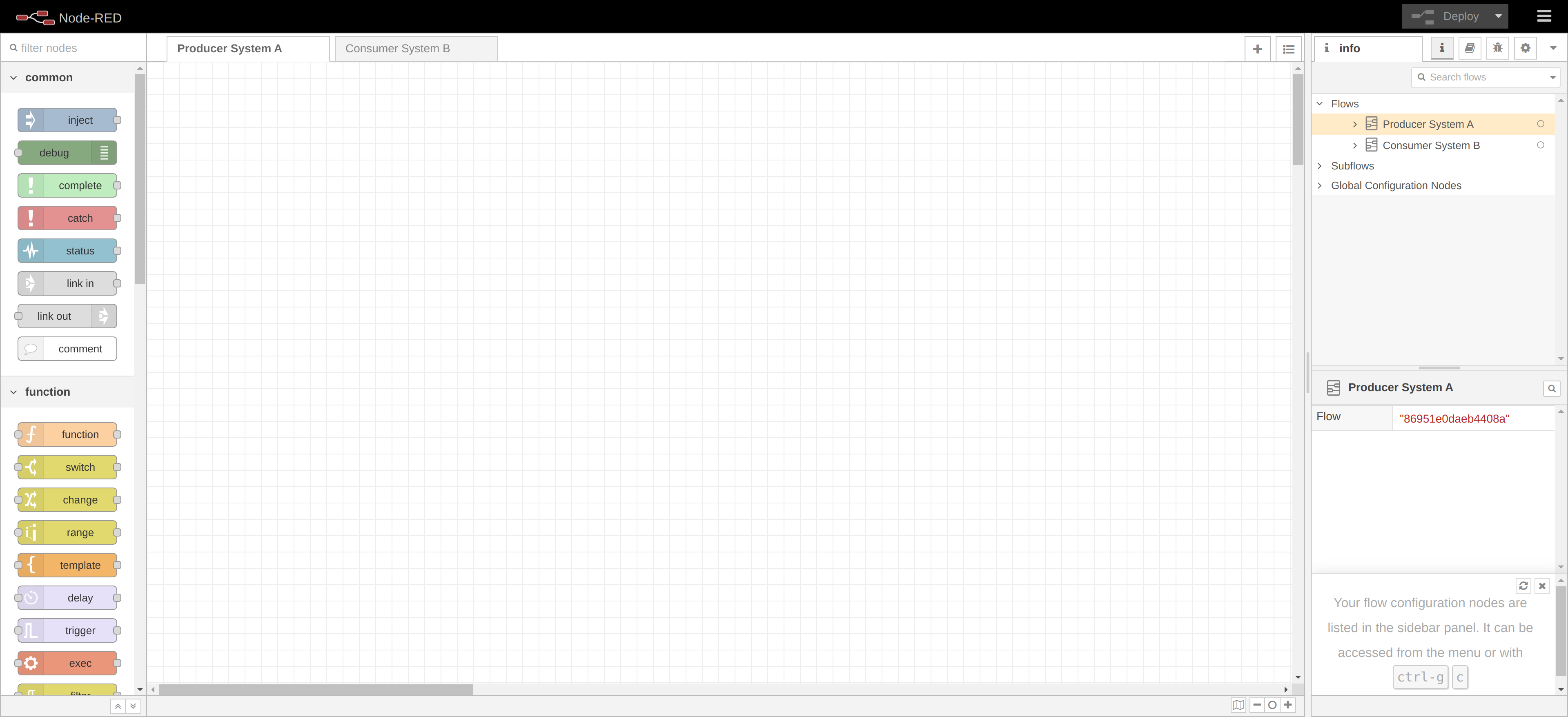
In the tab Producer System A, we are going to create a producer that sends data from the source node to the YouSolution.Cloud platform. In the tab Consumer System B, we are going to create a consumer that read data from the platform and send them to the target node.
Producer
First of all, we need a node, called "inject" node, that allows us to inject messages into a flow, either by clicking the button on the node, or setting a time interval between injects.
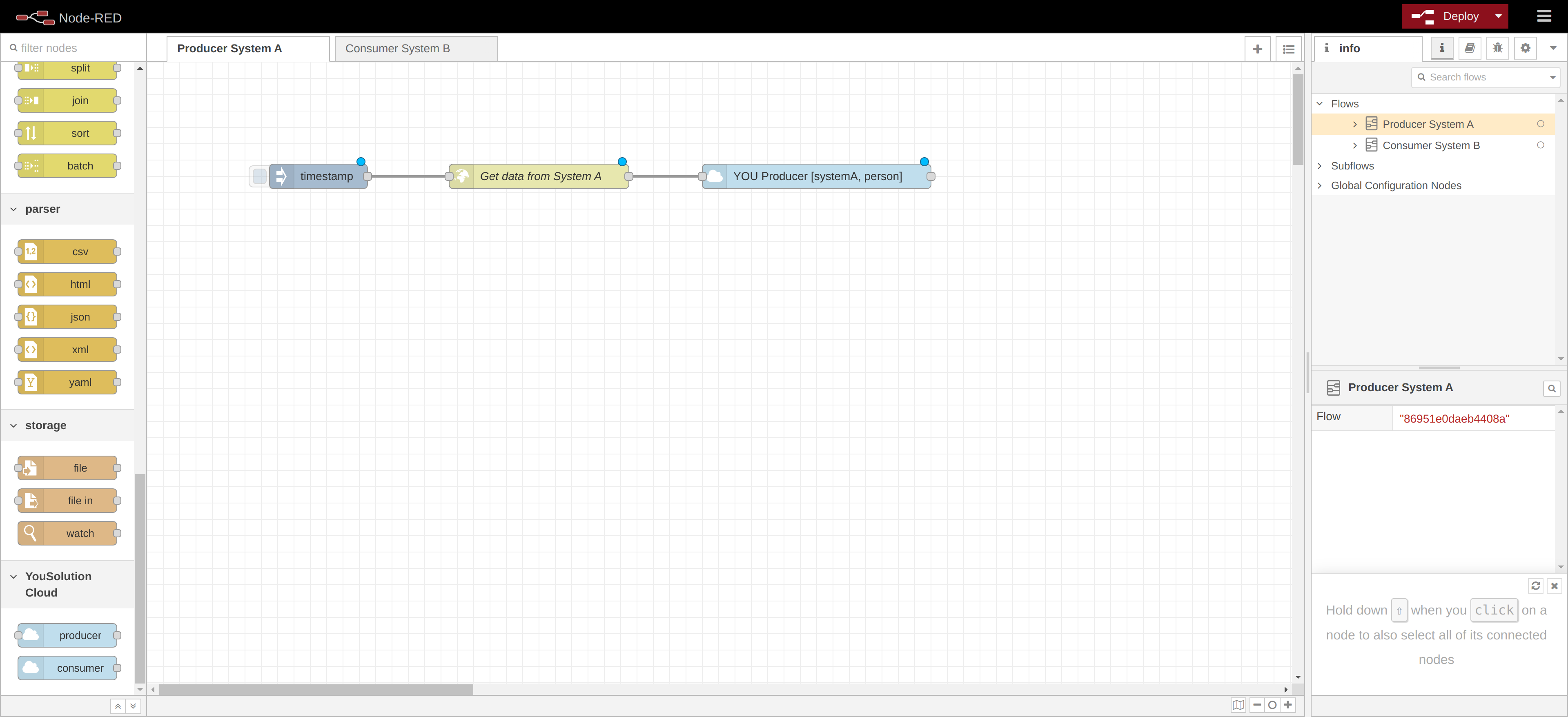
So drag the node named "inject" from the palette on the left side onto the workspace.
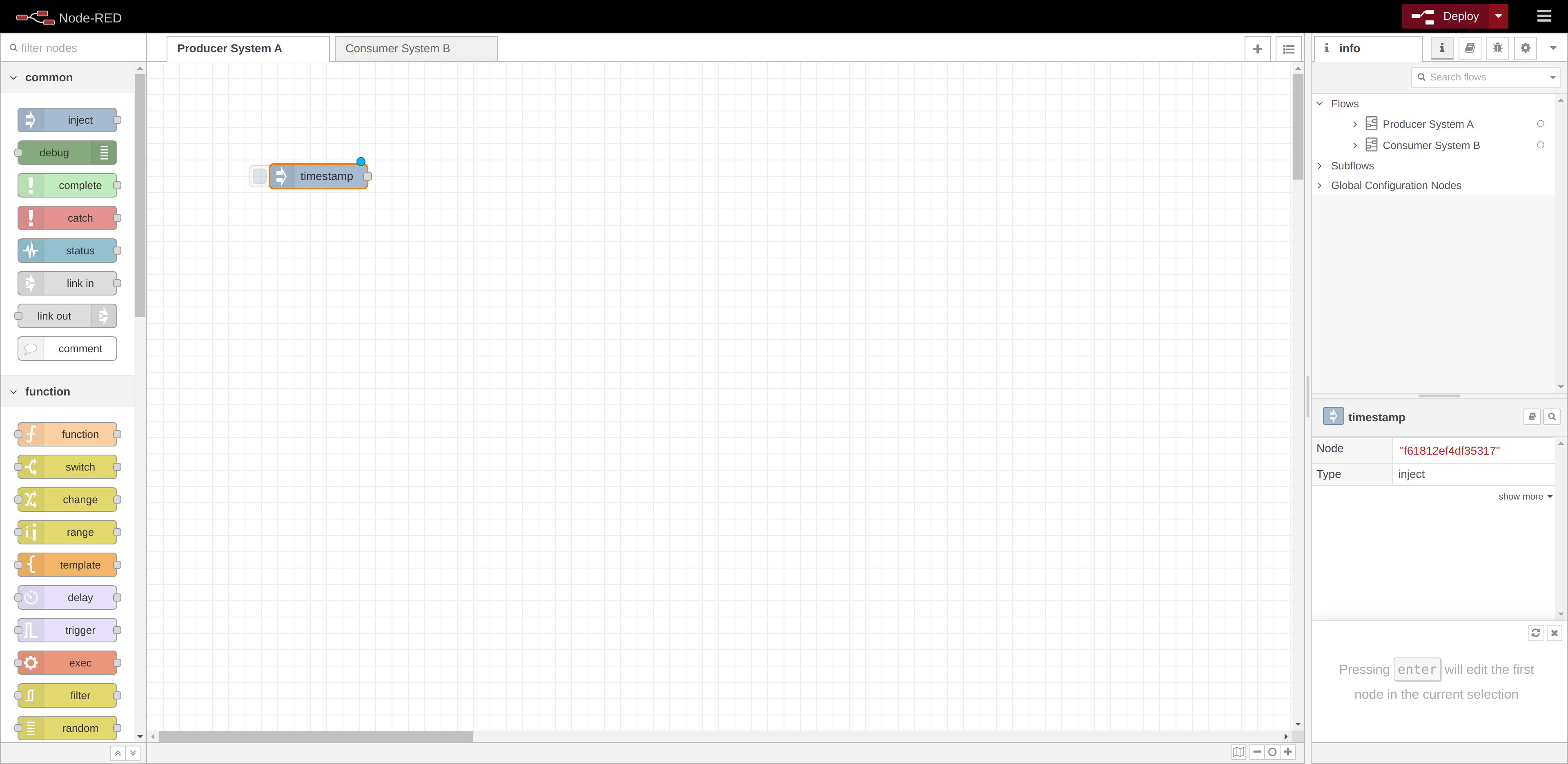
Select the newly added Inject node to see information about its properties and a description of what it does in the Information sidebar pane. Double click on the node to open the editor to modify it.
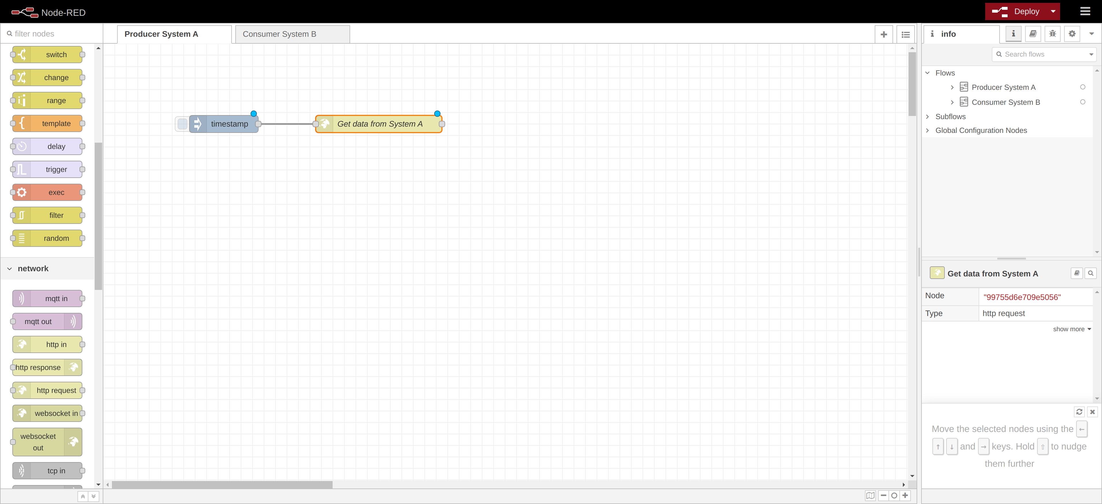
We use now a "http request" node to get the data to synchronize from the System A. For this example, we assume that we get the data by calling an exposed API of the System A, but there are many other ways to retrieve data.
Wire the two nodes together by connecting the "Inject" and "http request" (that we renamed "Get data from System A") nodes together by dragging between the output port of one to the input port of the other.
Now we have to send the data from the System A to the platform and, for this purpose, we want to use the node producer of the library @yousolution/node-red-contrib-you-yousolution.cloud, developed by YouSolution.Cloud.
NOTE
If you don't want to use the YouSolution.Cloud library, you can send data to the platform by using an http request node and calling the API POST:
https://api.yousolution.cloud/messages
and passing as query params the source node and the entity and as body an array with the messages to synchronize.
Example:
https://api.yousolution.cloud/messages?sourceNode=systemA&entity=person
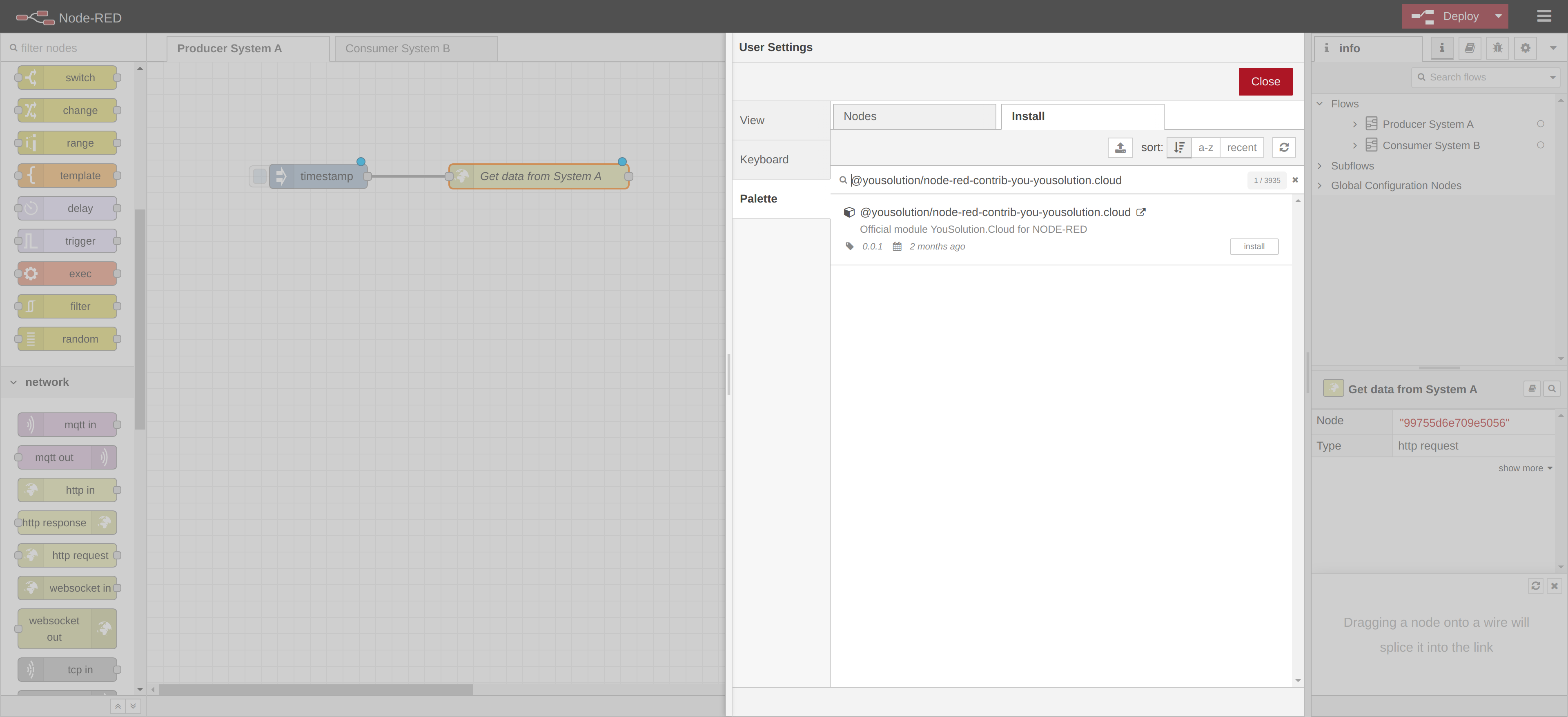
To install the library, click on the menu button on the right of the toolbar and select Manage palette.
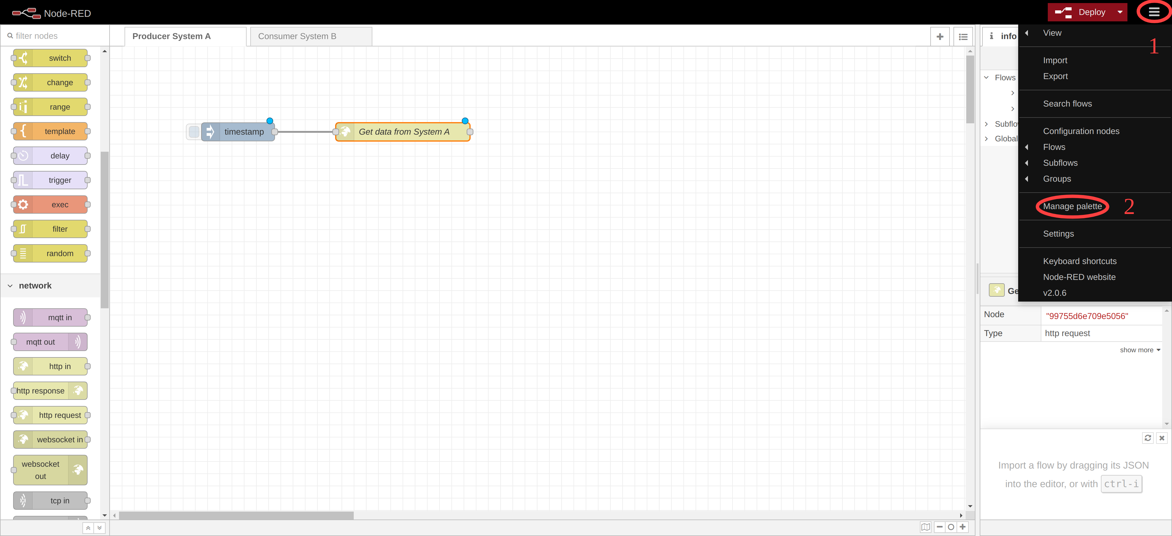
From this panel you can install external libraries that add new functionalities to Node-RED. Go in the tab Install and search "@yousolution/node-red-contrib-you-yousolution.cloud". Click on the button install to install it.
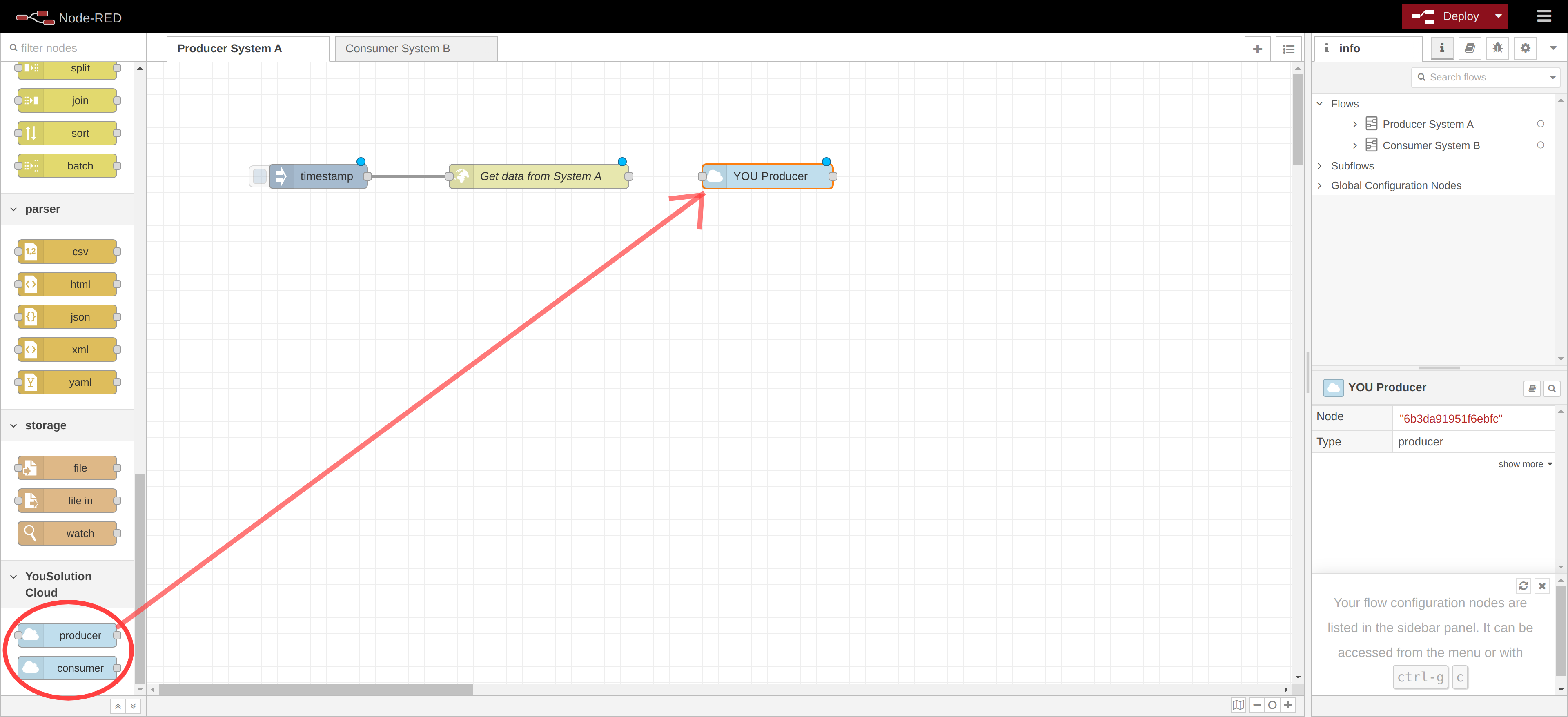
The newly installed nodes (producer and consumer) appears in the palette. Drag the node producer onto the workspace and select it to open the editor of the node.
The configuration of the producer is very easy. You have to fill in the field as displayed in the following image:
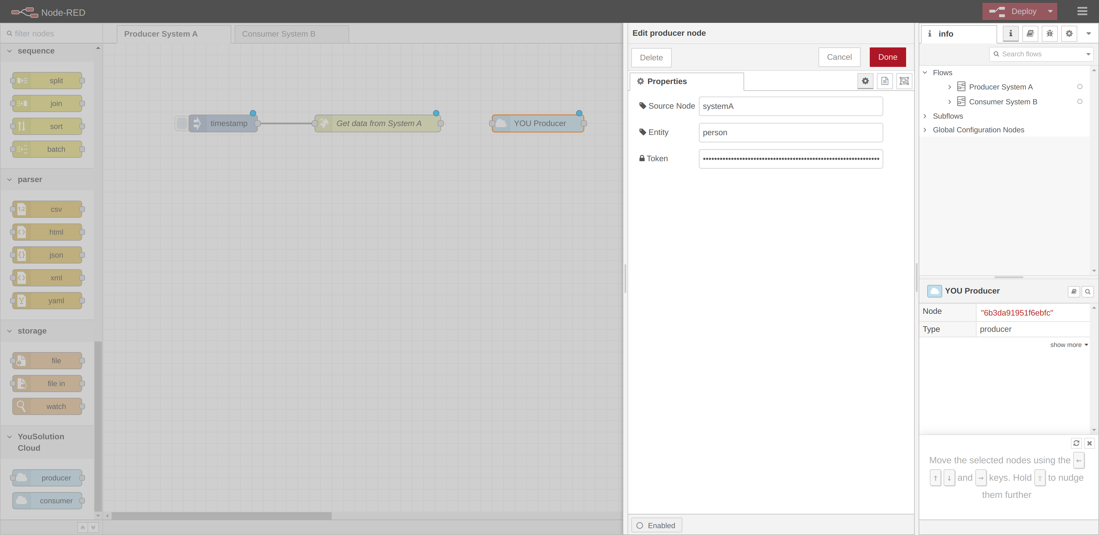
NOTE
The source node and the entity values to enter are their ids. You can find them from the list of the nodes and the list of the entity reachable from the Sync plan page. (see Delete a node or Delete an entity).
The producer node needs a bearer token to be authenticated. Go in the Sync Plan page and click on the button GET TOKEN:
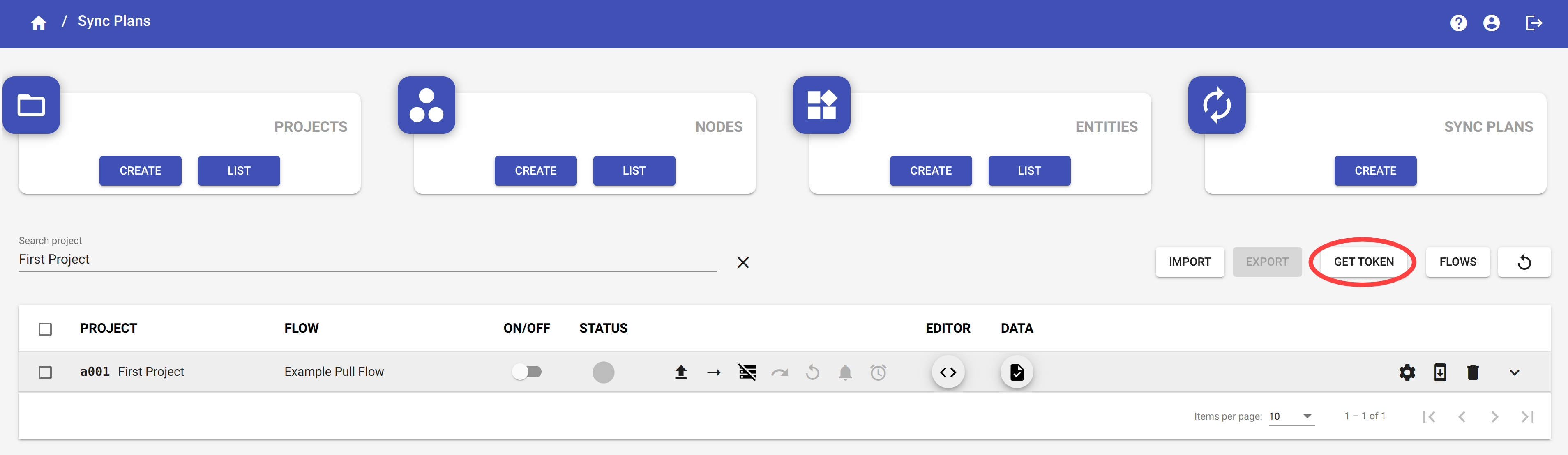
A dialog opens with the token. Click on the button Copy to copy the token.
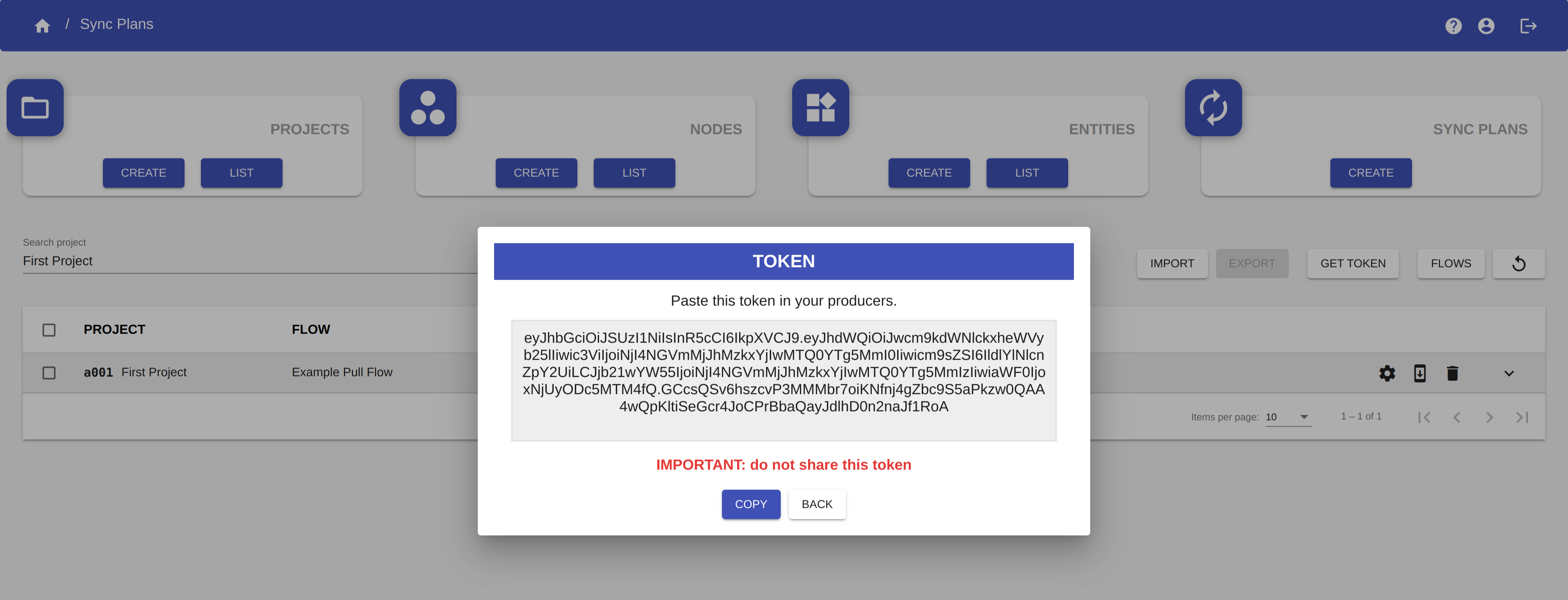
Return to the Node-RED page and paste the token on the field Token in the editor of the producer node.
Click Done to save changes and close the editor.
Wire the two nodes together by connecting the "Get data from System A" and "YOU Producer" nodes together by dragging between the output port of one to the input port of the other.
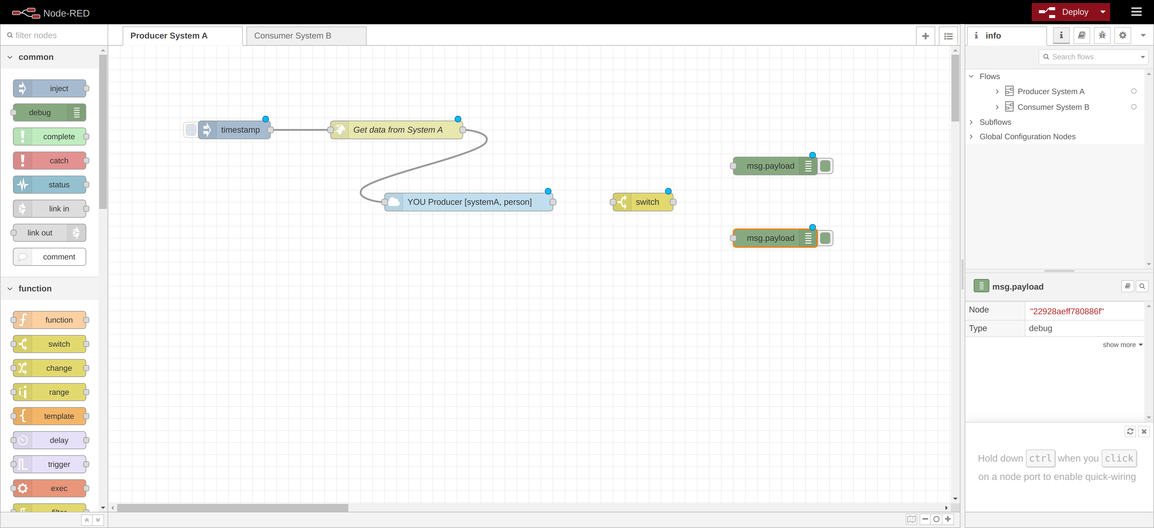
The last step is to catch the http response.
Drag onto the workspace the "switch" node and two "debug" nodes.
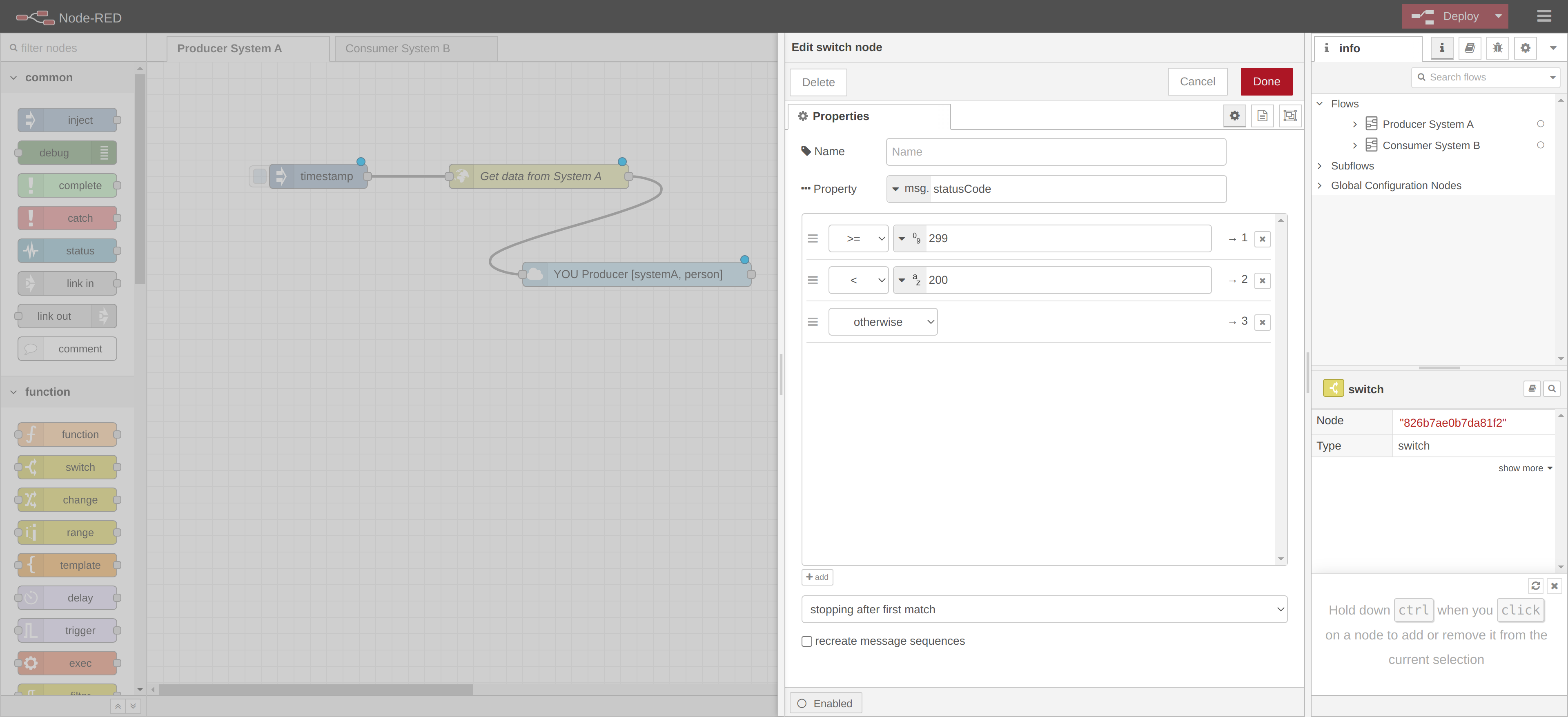
We use the "switch" node to route the messages according to the statusCode of the http response. The two "debug" nodes are used to display the success response or the error response.
Edit the "switch" node as the following:
Open the panel of the "debug" nodes and rename one of the nodes with name "Error" and the other with the name "Success". Wire the nodes as the following:
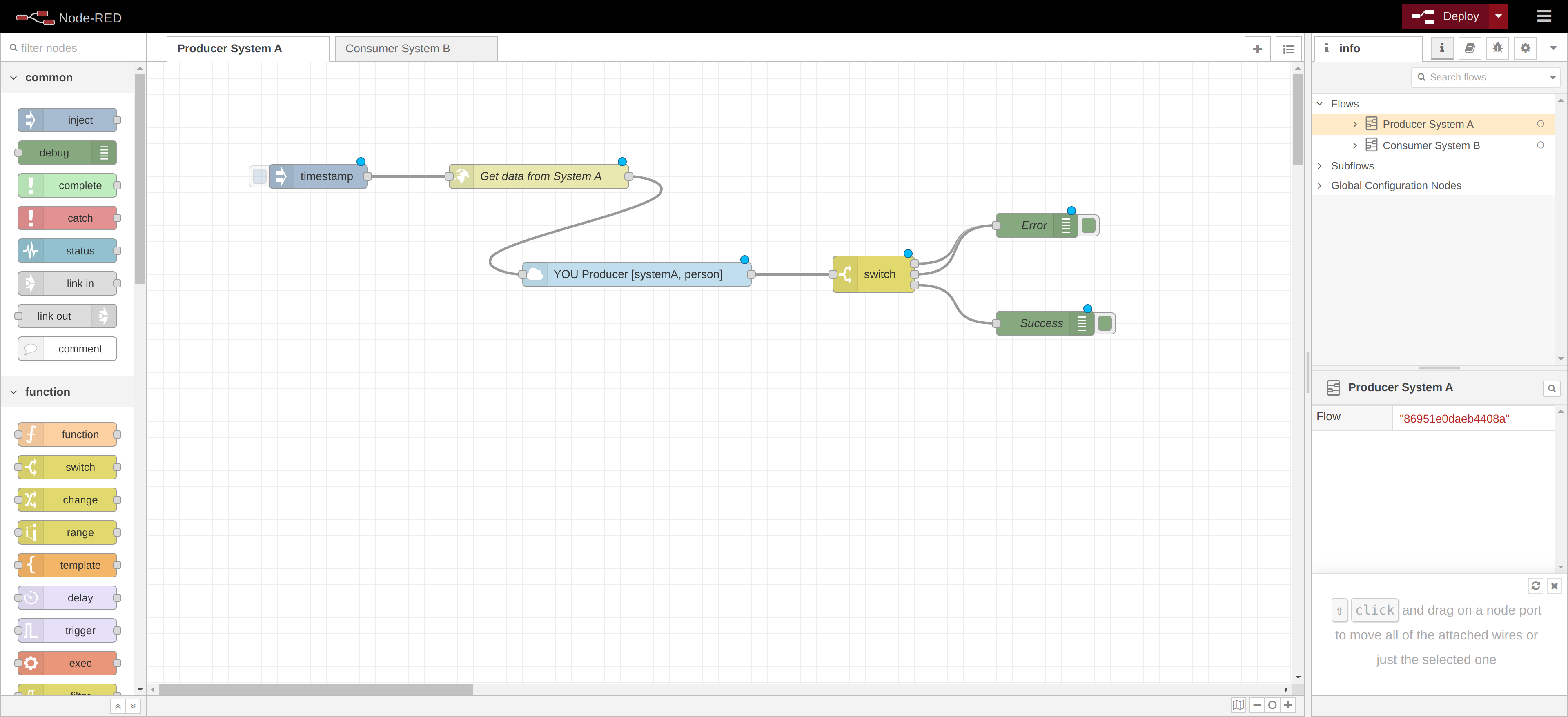
Click on the "Deploy" button on the toolbar to deploy the flow.
The producer is completed.
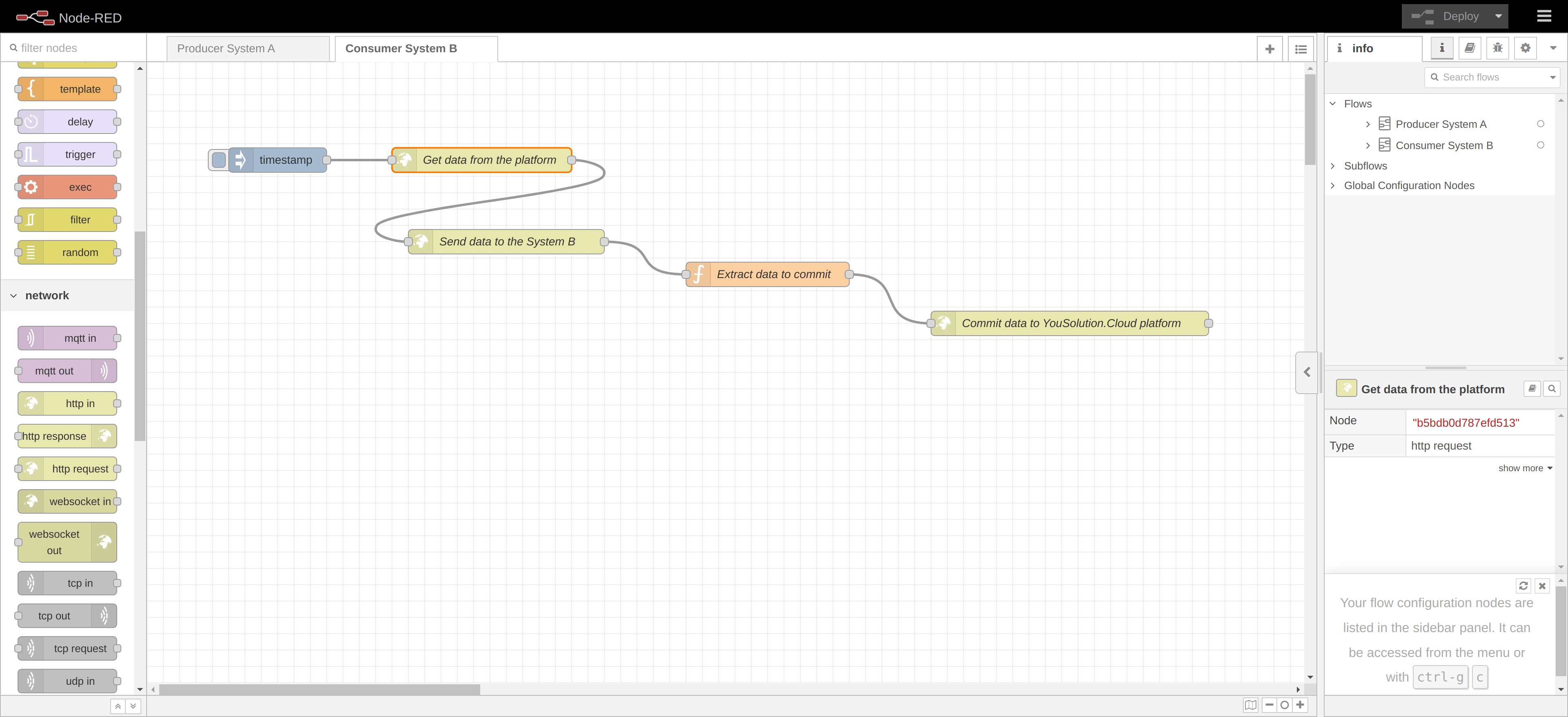
Consumer
The consumer of a pull flow has to make a request to the platform to get the synchronized data and send it to the target node.
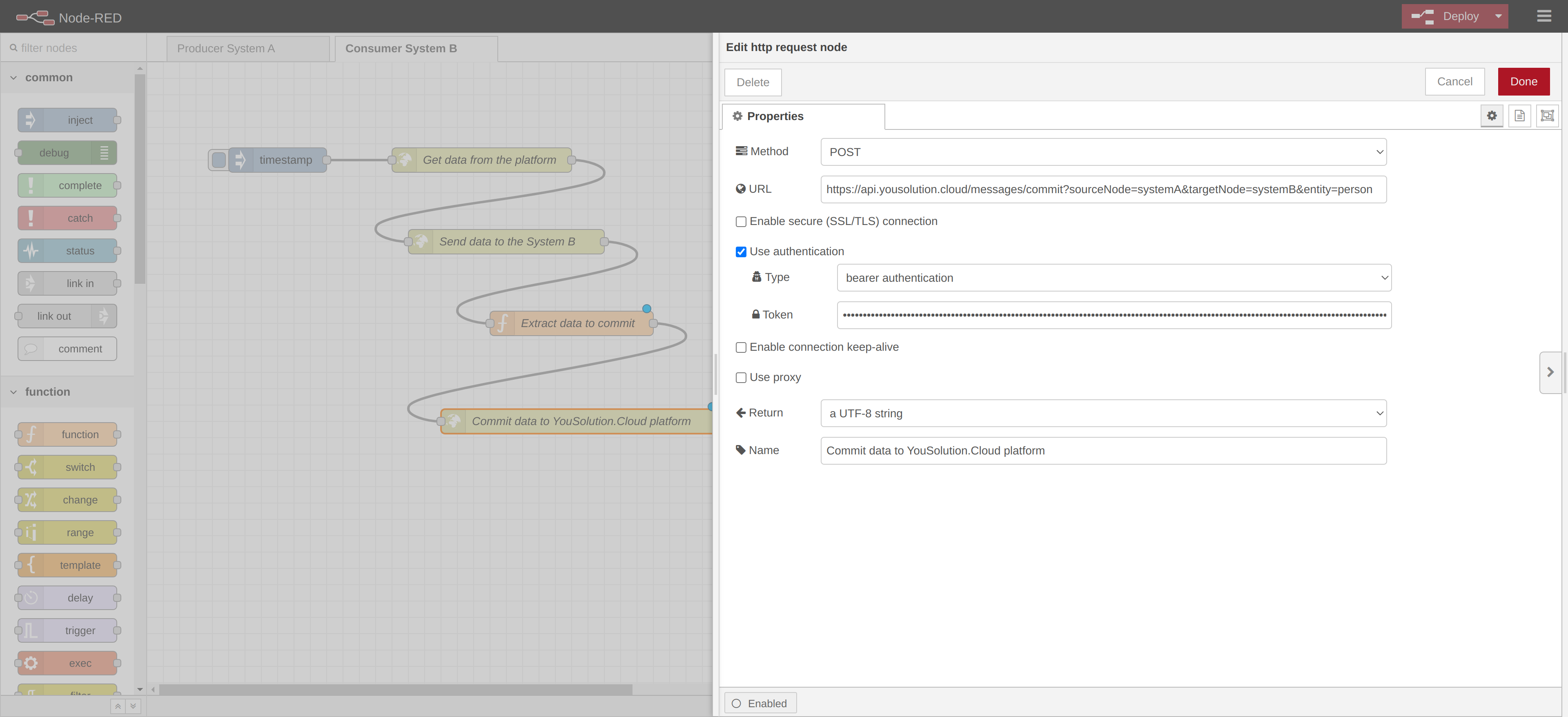
Go in the Consumer System B tab and drag an "Inject" node and a http request onto the workspace. Wire the two nodes together and edit the http request node as shown in the following image:
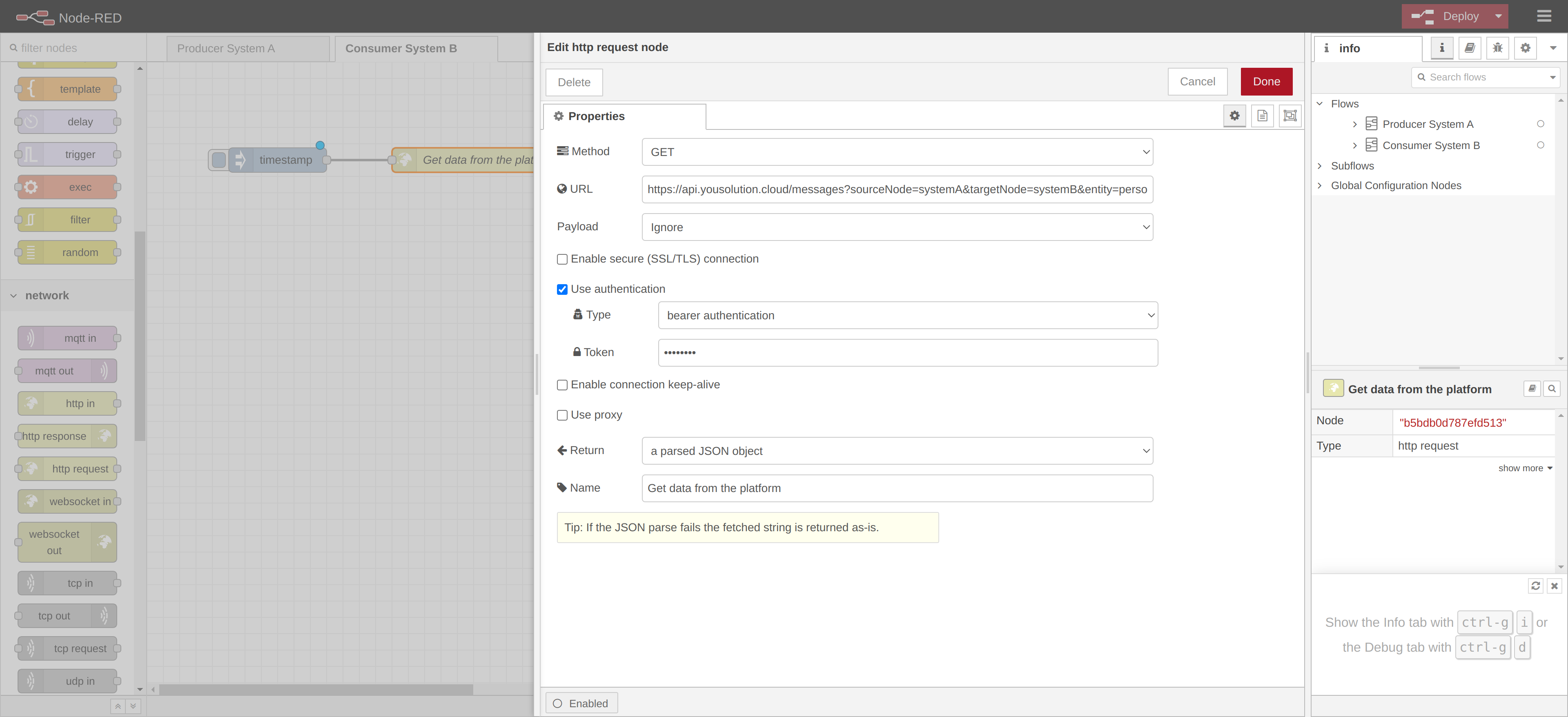
With the http request node, you make an http request to the plaftorm by calling the API GET:
https://api.yousolution.cloud/messages
You have to specify the source node, the target node and the entity as the query params.
EXAMPLE
https://api.yousolution.cloud/messages?sourceNode=systemA&targetNode=systemB&entity=person
This API needs an authentication token to be called, so set the bearer authentication and insert the same token used for the producer.
This API returns the data in the synced queue of the target node (if there is any). This data has been synchronized by the platform and is now waiting to be sent to the target node.
Once the data is received from the platform, you have to send it to the target node. Use another http request node to do it.
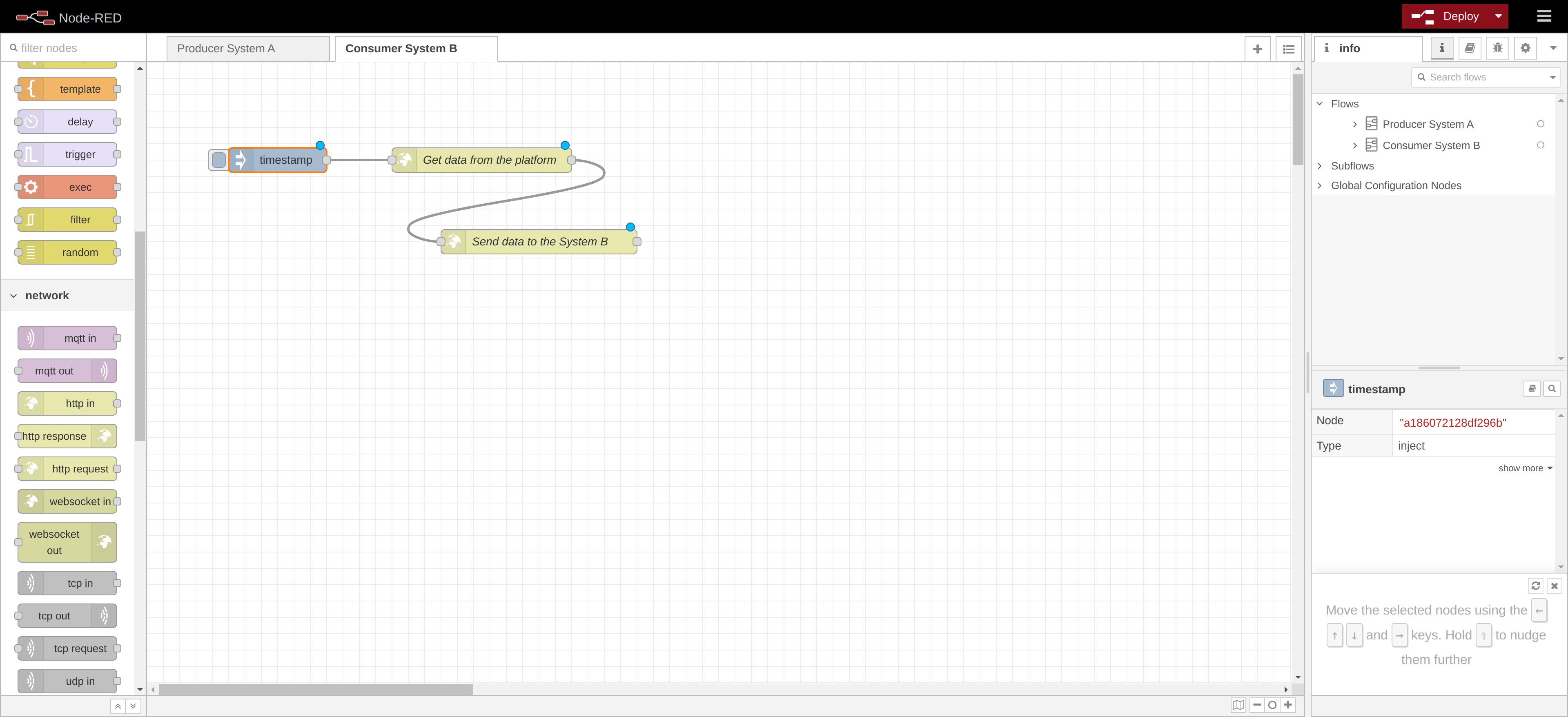
NOTE
It might be necessary to manipulate the data taken from the plaftorm before sending it to the target node. Use a function node to do it.
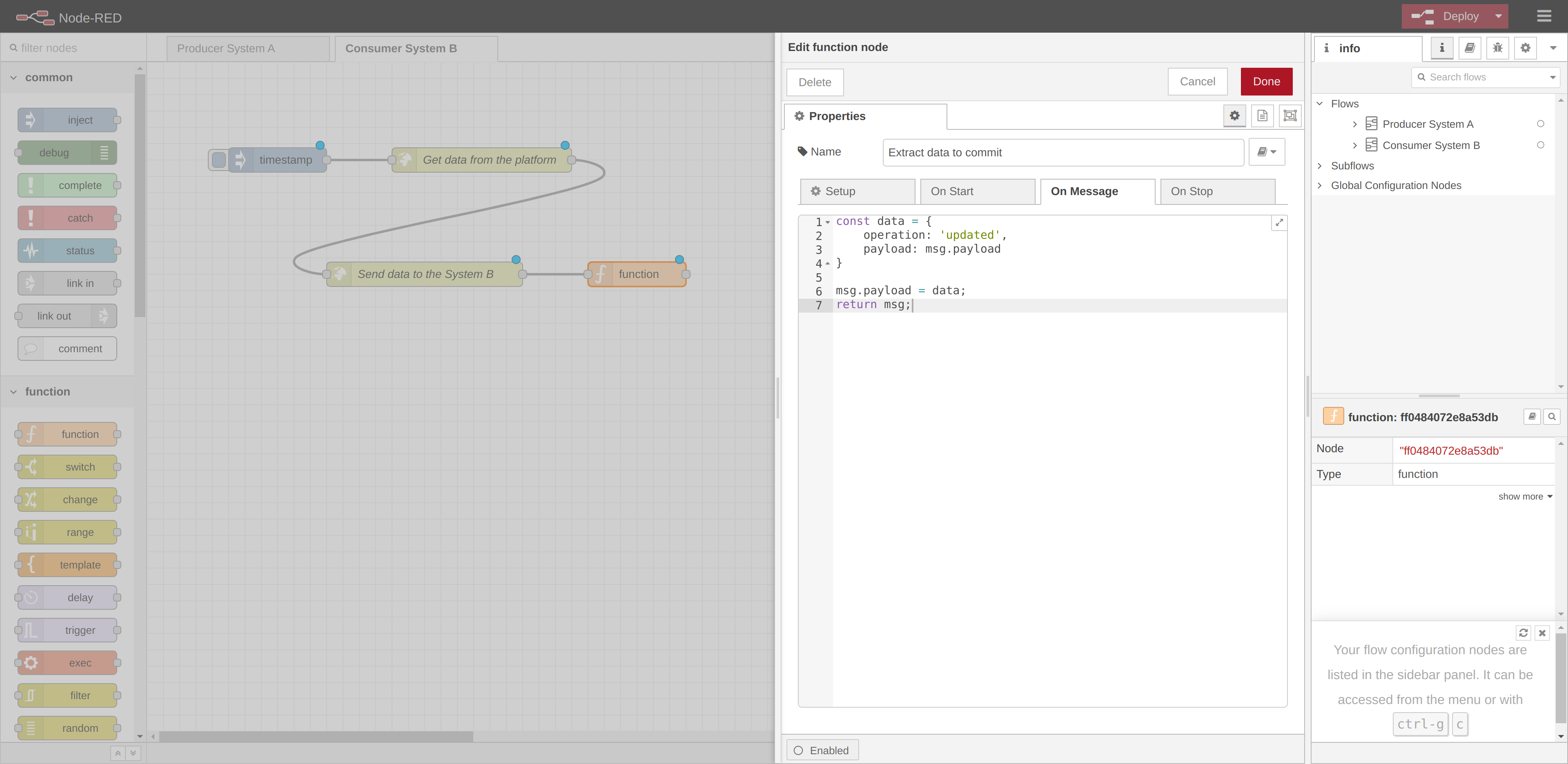
When the data has been successfully written in the target node, you have to commit the data to the platform. Commiting a data means that it will be marked in the platform as received by the target node and will no longer be available in the queue, so the queue can process the next data.
To commit a data, you have to call the following API POST:
https://api.yousolution.cloud/messages/commit
You have to specify the source node, the target node and the entity as the query params, and the data to commit as the body.
EXAMPLE
https://api.yousolution.cloud/messages/commit?sourceNode=systemA&targetNode=systemB&entity=person
The body must have the following format:
{
  operation: 'updated',
  payload: {
    name: 'John Smith',
    age: 32,
    address: '21457 Central Square, Miami, Florida'
  }
}
The field payload must contain the data to commit.
This API needs an authentication token to be called, so set the bearer authentication and insert the same token previously used.
In this example, we take the response from the node Send data to the System B and send it in the body of the API to commit the data. We use a function node to format the data to send.
Now you call the API to commit the data by using a http request node:
Click on the "Deploy" button on the toolbar to deploy the flow.
The consumer is completed.
NOTE
Note that the target node has to make a request to get the data from the platform, as provided in the PULL strategy.
Start synchronization
Now we can start synchronization. If you return in the Sync Plan page, you will see that the status icon of the sync plan is grey. This means that the sync plan is correctly compiling and the synchronization is off.
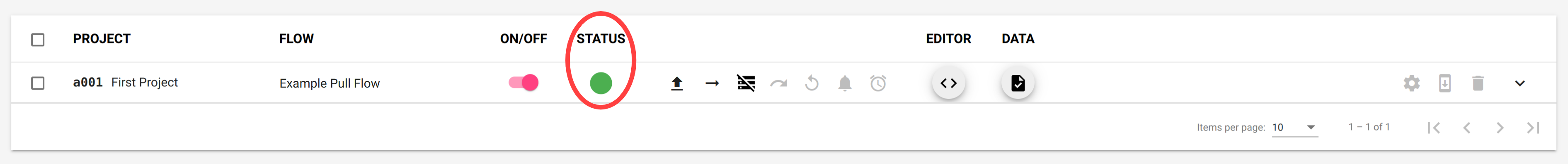
Switch on the ON/OFF button to start the synchronization. The Status icon will turn green to indicate that the synchronization is on.
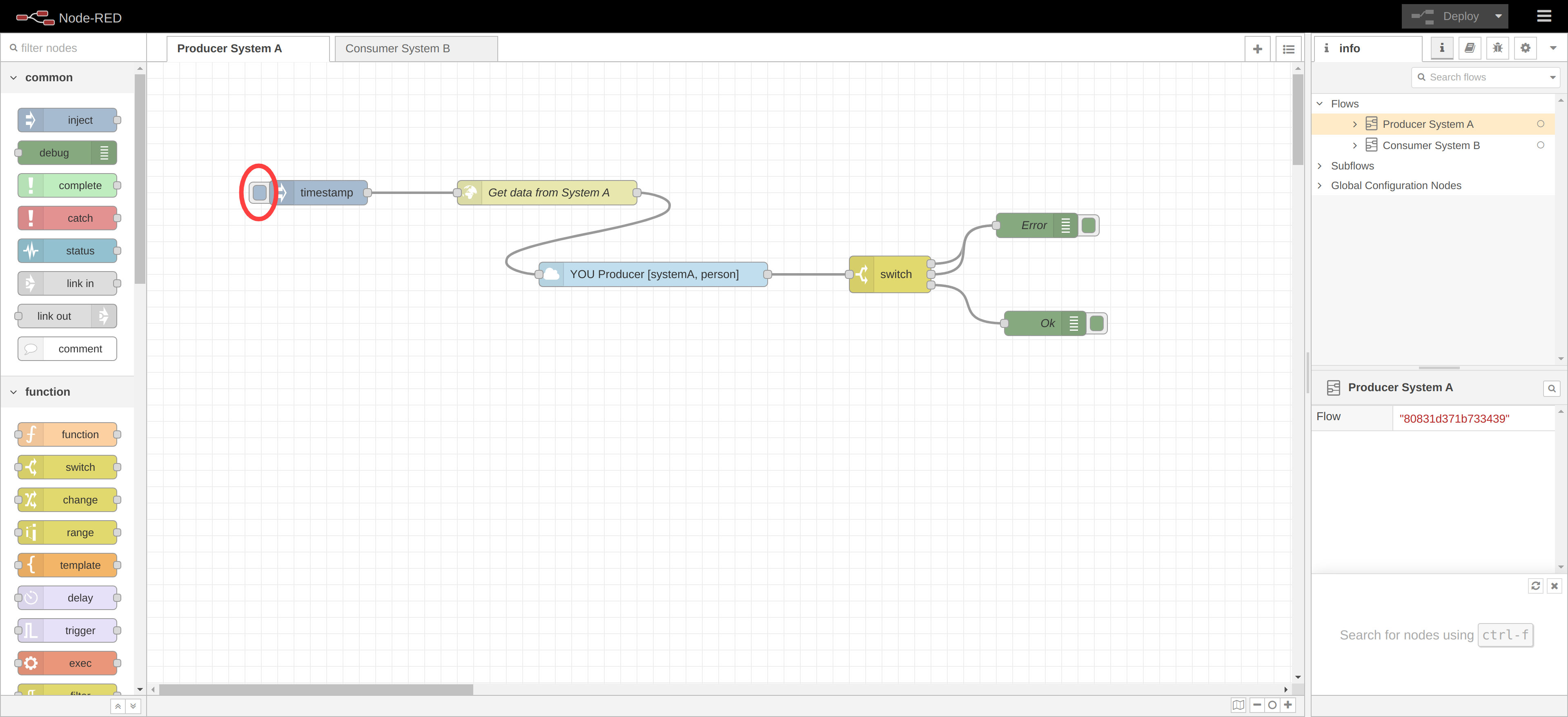
Now we have to send a message from the source node. Go into the Node-RED page in the Producer System A tab and press the button on the left the timestap button.
This will trigger a request for the data to the System A and then this data will be sent to the platform by the "producer" node.
If you return to the Sync Plan page, you should see that an icon is appeared under the status of the Sync Plan to indicates that there are one or more messages in the queues that are ready to be read by the consumer.
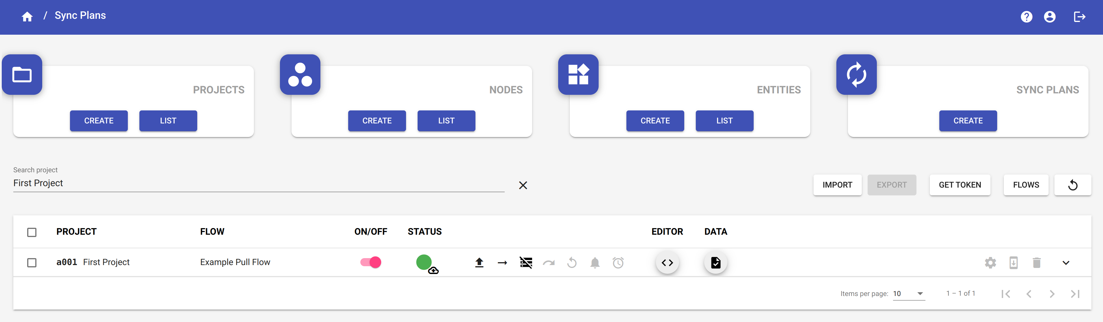
By clicking on the Sync plan status icon you can visualize the queue in which are stored the messages.
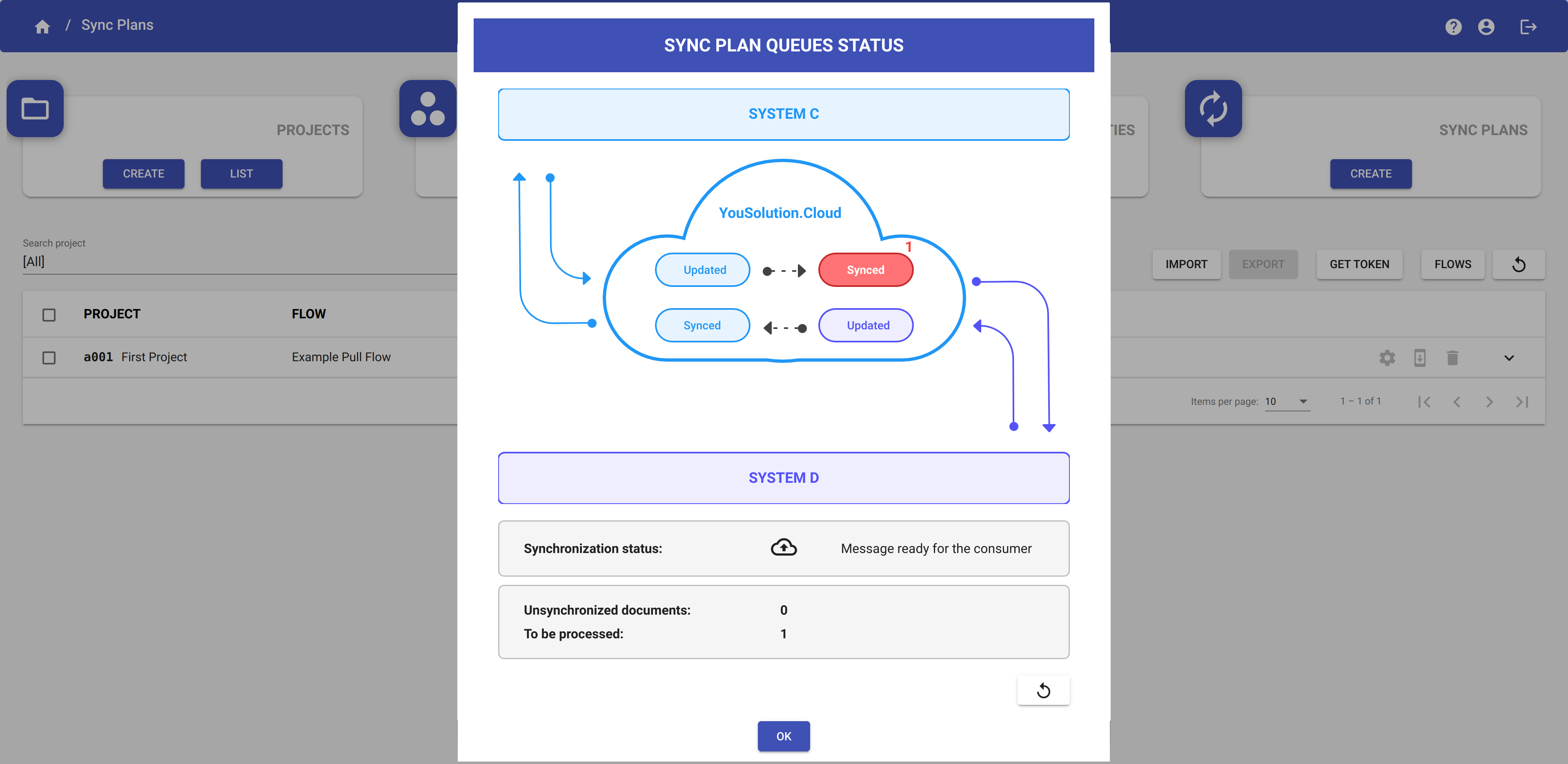
Now the target node can make a request to get the data.
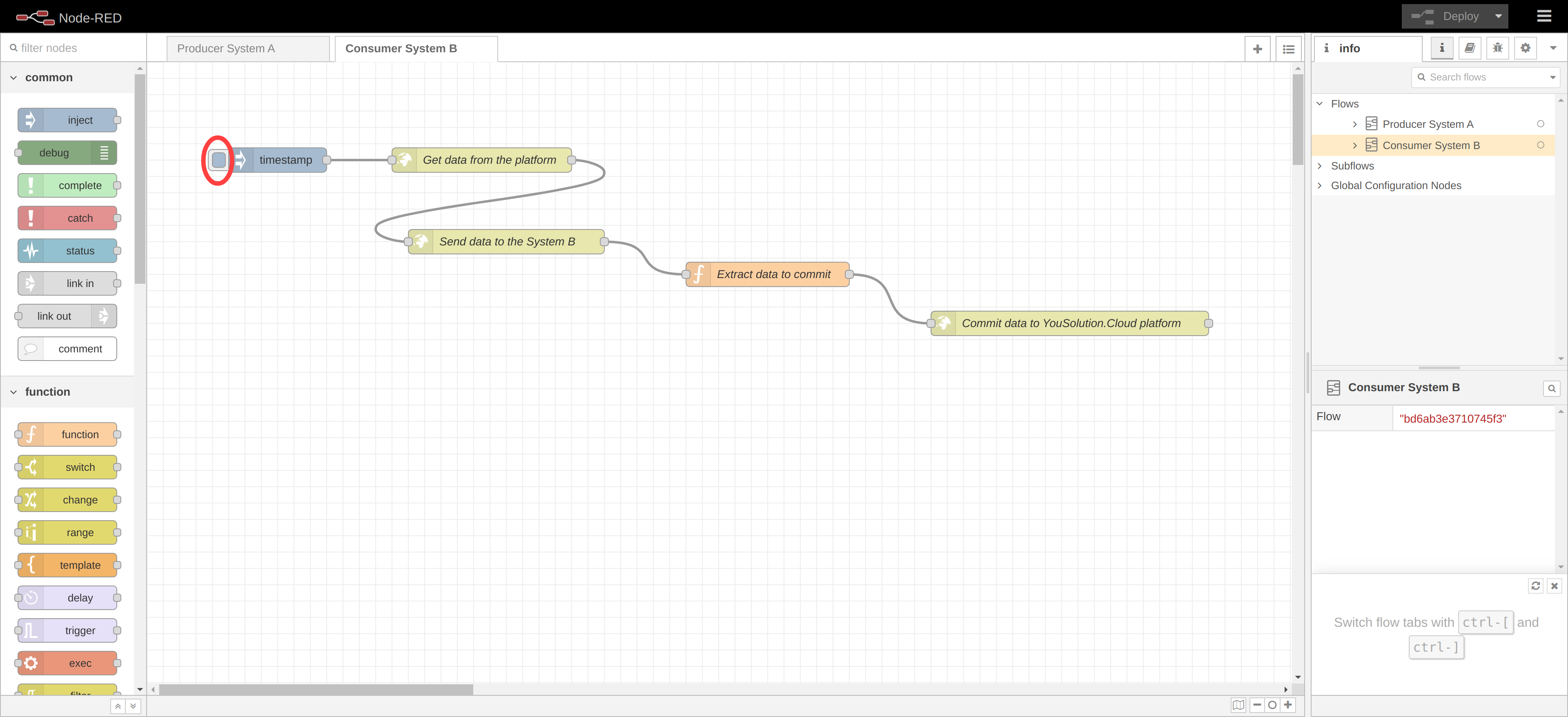
Go in the Consumer System B tab in Node-RED and press the button on the left the timestap button.
This will trigger a request for the data to the platform and then this data will be sent to the target node. When the target node returns the response, the data will be commited in the platform.
Warning
You should commit a data only when the data is successfully received by the target node.
Remember that when you commit a data, this data will no longer be available on the queue of the platform.
Return into the Sync Plan page and click on the button DATA to access the page that shows the synchronized documents.
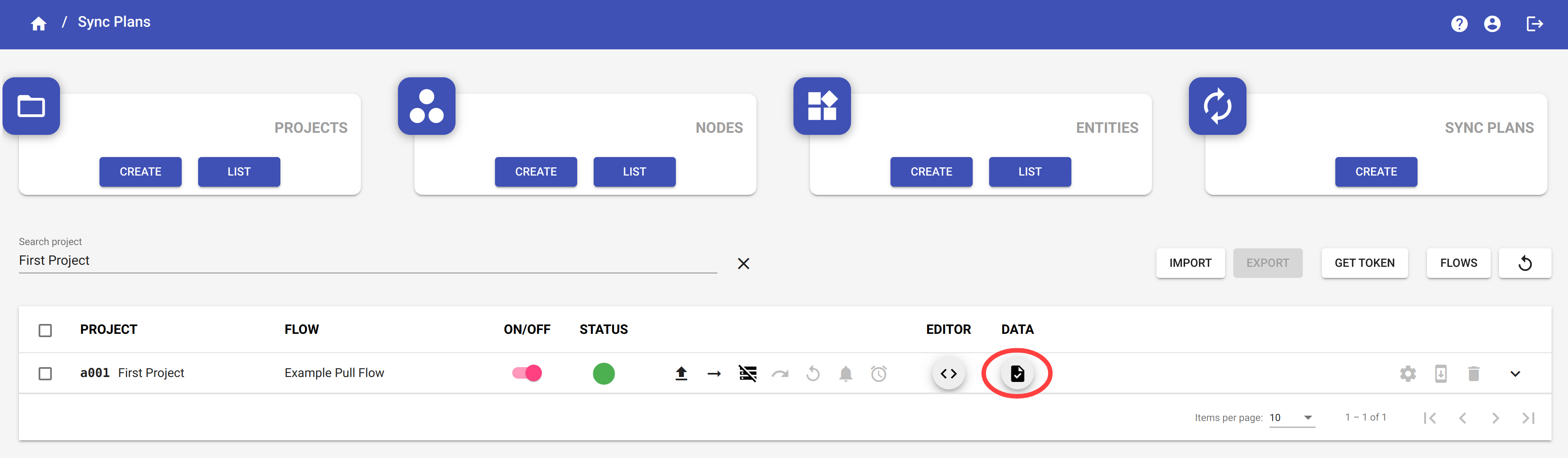
Here you can visualize the synchronized documents.
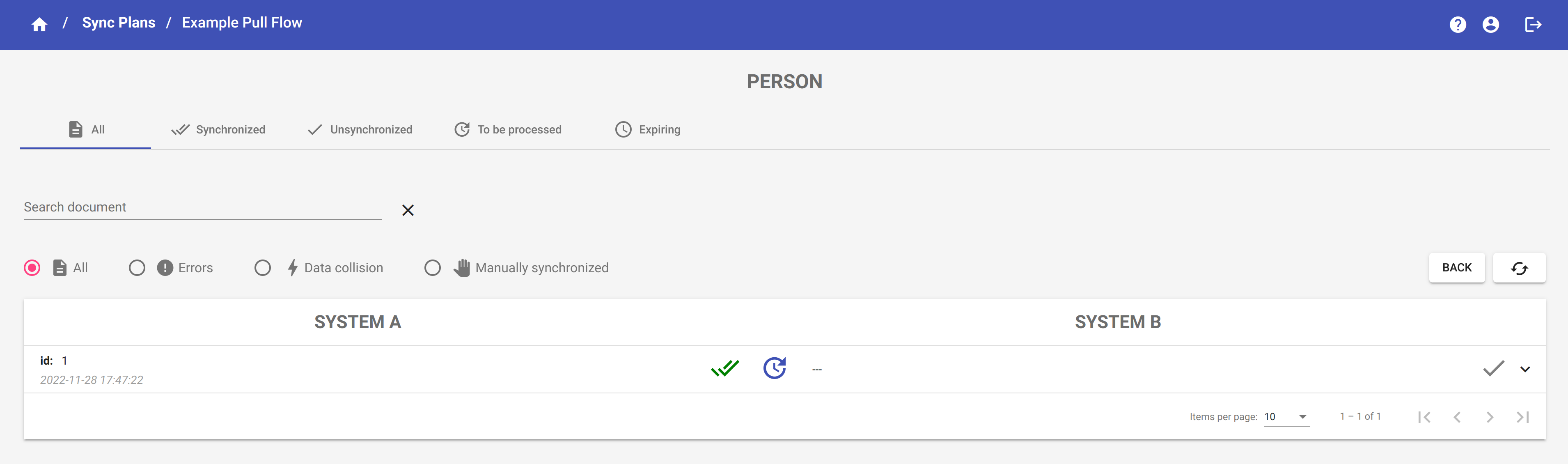
The icon ![]() means that the synchronization of this document has not been completed yet.
means that the synchronization of this document has not been completed yet.
When the synchronization of the document has been completed, the icon ![]() appears to indicate the synchronization direction.
appears to indicate the synchronization direction.
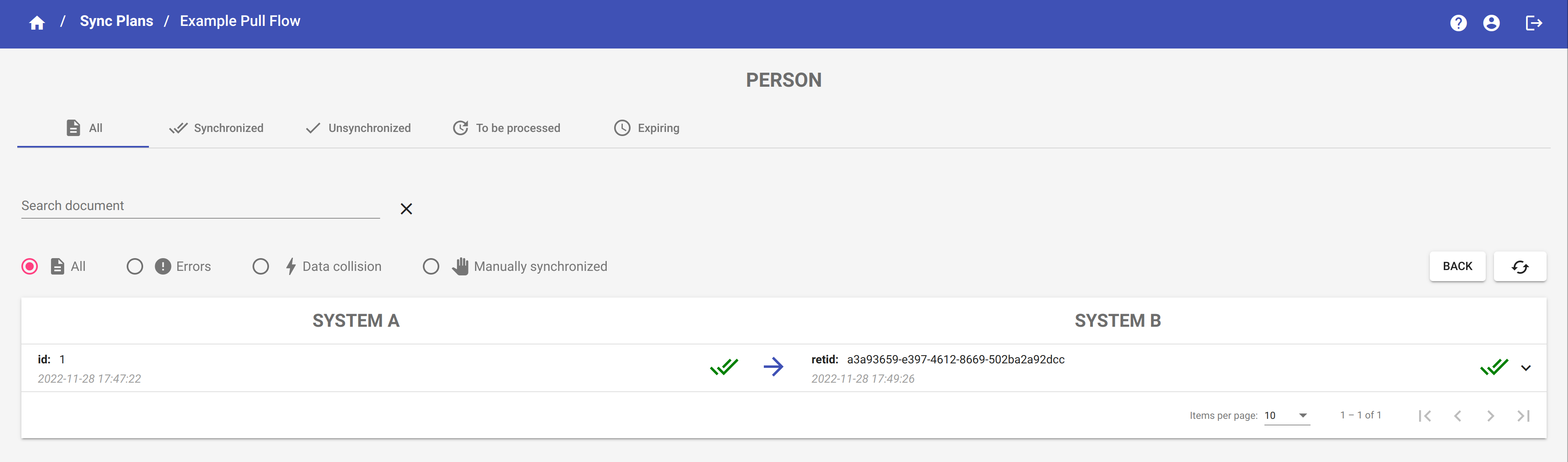
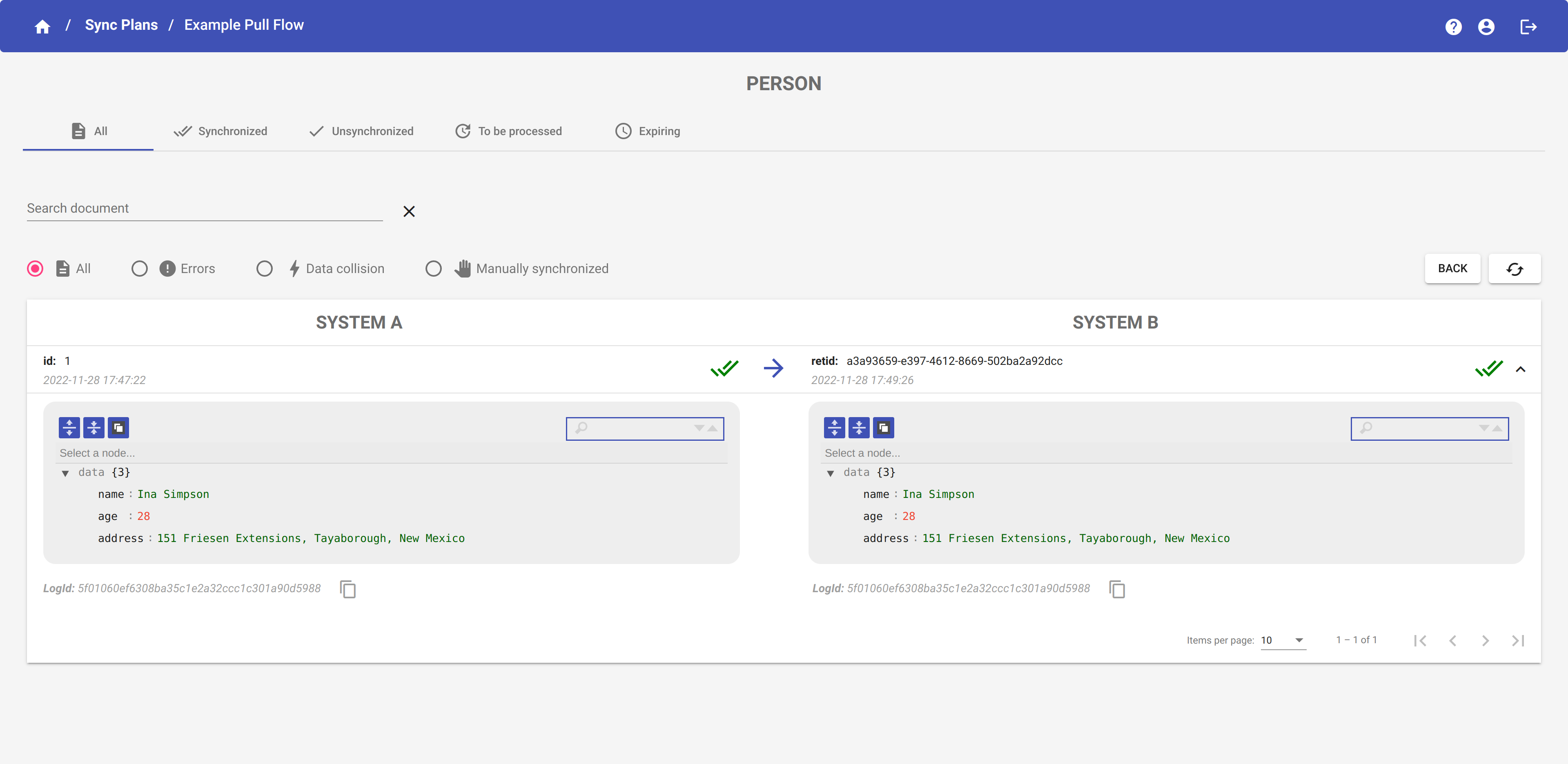
As you can see, the message that we have just sent from System A to System B has been successfully synchronized. Click on the row to expand it and visualize the entire message.
The Documents page is divided in four tabs:
- All: it shows all the documents sent to the platform during the synchronization, both those successfully synchronized and those unsynchronized ones.
- Synchronized: it shows only the documents successfully synchronized.
- Unsynchronized: it shows only the documents not successfully synchronized.
- Expiring: it shows the expiring documents.
NOTE
-
The icon
 indicates that the data is successfully synchronized in the node.
 -
The icon
 indicates that the data is not successfully synchronized in the node.
 -
The icon
 indicates that there are one or more synchronization error in the node.
 -
The icon
 indicates that the data is successfully synchronized in the node, but it contains also one or more errors occurred during the synchronization.
 -
The icon
 indicates that a data collision occurred. It means that the node has returned data that is different from the data sent by the platform to that node.
 -
The icon
 indicates that the synchronization of the document has not yet been completed.
 -
The icon
 indicates that the synchronization of the document has been completed. The direction of the arrow goes from the node that sent the data to the node that received it.
A document is successfully synchronized only when both source node and target node have been marked with the icon ![]() .
.
For more info about the operations you can do with the documents, see the section Documents
Sync Plan Status
You can check the status of your synchronization by monitoring the STATUS column in the Sync Plan table.
For a complete explanation of all the possible states of a Sync Plan, please visit the sections Sync Plan Status and Sync Plan Status Events.
For a complete explanation of all the operation you can do with the sync plans, please visit the section Sync Plans